Minimally invasive surgery clamp for abdominal cavity

A minimally invasive surgery and jig technology, applied in the fields of surgery, small surgical forceps, medical science, etc., can solve the problems of impossible disassembly and separation or temporary assembly by doctors, and achieve the effect of simple operation and large clamping force.

Active Publication Date: 2018-06-01
汕头市颂美恩生物科技有限公司
View PDF7 Cites 5 Cited by
  • Summary
  • Abstract
  • Description
  • Claims
  • Application Information

AI Technical Summary

Problems solved by technology

[0007] First, in the existing forceps clip, the clip body, the intermediate connecting pipe, and the control part are designed in an integrated manner, that is, the three cannot be disassembled, separated or temporarily assembled by the doctor during the operation

Method used


Image

  • Minimally invasive surgery clamp for abdominal cavity
  • Minimally invasive surgery clamp for abdominal cavity
  • Minimally invasive surgery clamp for abdominal cavity

Examples


Embodiment 2

[0072] The elastic clamp body 1 of this embodiment two is a kind of clamp, and when its metal wire 4 is in relaxed state (normal state), its jaw 10 is opened, as Figure 17 As shown; when the metal wire 4 is pulled upwards, the jaw 10 is closed, and the closed state is as Figure 16 As shown, the rest of the structure of the second embodiment is the same as that of the first embodiment.

Embodiment 3

[0074] The elastic clamp body 1 of the third embodiment is a clamp with a normally closed jaw, which includes two elastic clamp arms 11, each elastic clamp arm 11 includes a clamp arm rear section 111 and a clamp arm front section 112, and the clamp arm The front section 112 is connected to the clamping part 12, and the rear sections 111 of the two clamp arms are connected together in a figure-eight shape. The front sections 112 of the two clamp arms form a cross structure. Under normal conditions, the rear sections 111 of the two elastic clamp arms are naturally opened and Keep the jaw between the two clamping parts 12 in a closed state, such as Figure 18 As shown; when the clamp arm rear section 111 of the two elastic force clamp arms was pressed by the taper of the front end of the clamp body accommodation section 21 and gathered, the jaw between the two clamping parts 12 opened, as Figure 19 shown.

[0075] The structure of other aspects is the same as that of Embodimen...

Embodiment 4

[0078] The difference between the fourth embodiment and the first embodiment mainly lies in the difference of the pressing components. In the fourth embodiment, instead of the tightening bolt 63 , the tightening member adopts a cam mechanism, and the rotation angle of the cam 9 is controlled by the handle 91 . When the high point of the cam 9 was aligned with the wire 4, the cam 9 pressed the wire on the hole wall of the small hole for threading the wire, so that the wire 4 could not move relative to the wire locking member 6, as Figure 21 As shown; when the low point of the cam 9 is aligned with the wire 4, the cam 9 leaves the wire and the wire is relaxed, as Figure 22 shown. The structure of the fourth embodiment is the same as that of the first embodiment.


PUM


Abstract

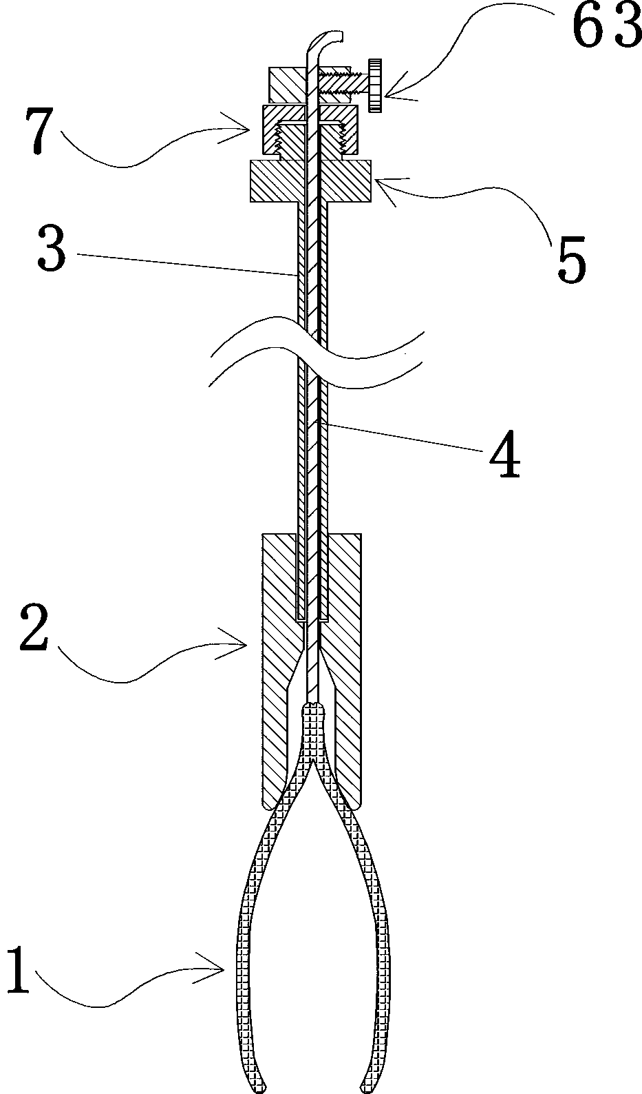
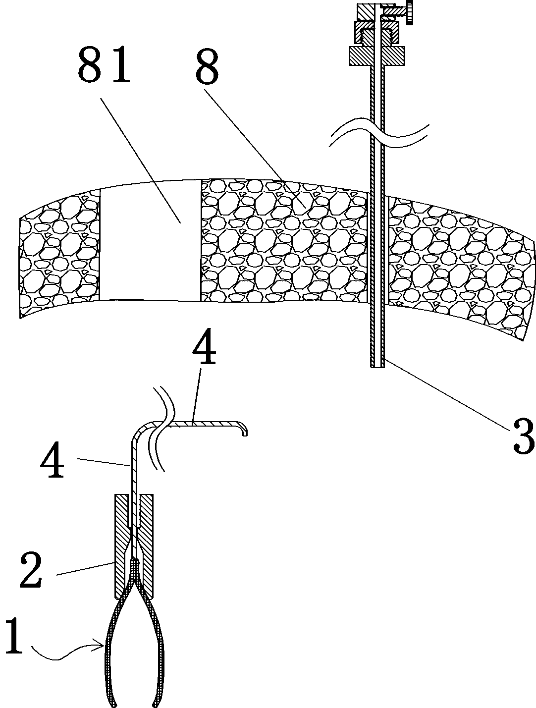
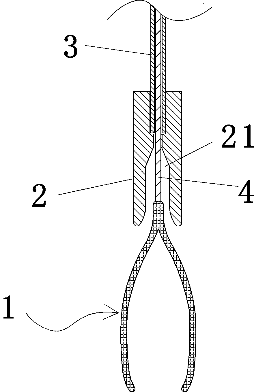
The invention provides a minimally invasive surgery clamp for the abdominal cavity. The minimally invasive surgery clamp for the abdominal cavity comprises an elastic clamp body and a metal wire, wherein the inner end of the metal wire is fixedly connected with the rear end of the elastic clamp body; the minimally invasive surgery clamp is further provided with a hollow round metal sleeve and an auxiliary control block, a through hole running through the axial full length is formed in the middle of the auxiliary control block, the through hole comprises a clamp body accommodating section, a necking down section and a metal sleeve accommodating section, the front end part of the clamp body accommodating section is in the shape of a horn mouth with the large front part and the small rear part, the hole diameter of the metal sleeve accommodating section allows the insertion of the inner end of the round metal sleeve, and the hole diameter of the necking down section is greater than the diameter of the metal wire and smaller than the outer diameter of the round metal sleeve. For the minimally invasive surgery clamp for the abdominal cavity, the needed size of an operation hole is freeof the limitation of the size of clamp arms of the clamp body, the needed hole diameter of the operation hole is small, the clamping of the clamp arms is powerful, and the operation is simple and convenient.

Description

technical field [0001] The invention belongs to the technical field of abdominal minimally invasive surgical instruments, in particular to a clamp for abdominal minimally invasive surgery. Background technique [0002] Minimally invasive abdominal surgery is popular among patients due to its small wound and quick recovery. In the process of minimally invasive abdominal surgery, a variety of surgical instruments need to be inserted into the abdominal cavity at the same time for coordinated operation. At the same time, each instrument for coordinated operation needs to have an operation hole, so it is necessary to drill multiple operation holes in the patient's abdominal wall, generally 3 to 5. Obviously, the smaller the diameter of the operation hole drilled on the patient's abdominal wall, the more likely it is to avoid leaving obvious scars on the body surface after surgery, and it is more conducive to reducing the damage to normal tissues of the human body, reducing the c...

Claims


Application Information

Patent Timeline
Patent Type & Authority Applications(China)
IPC IPC(8): A61B17/30A61B17/02A61B17/00
Inventor 蔡长茂陈燕婵陈凯平
Owner 汕头市颂美恩生物科技有限公司
Why Eureka
Try Eureka