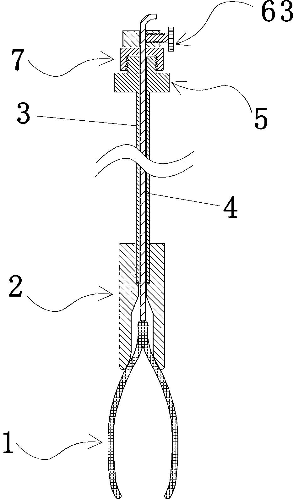
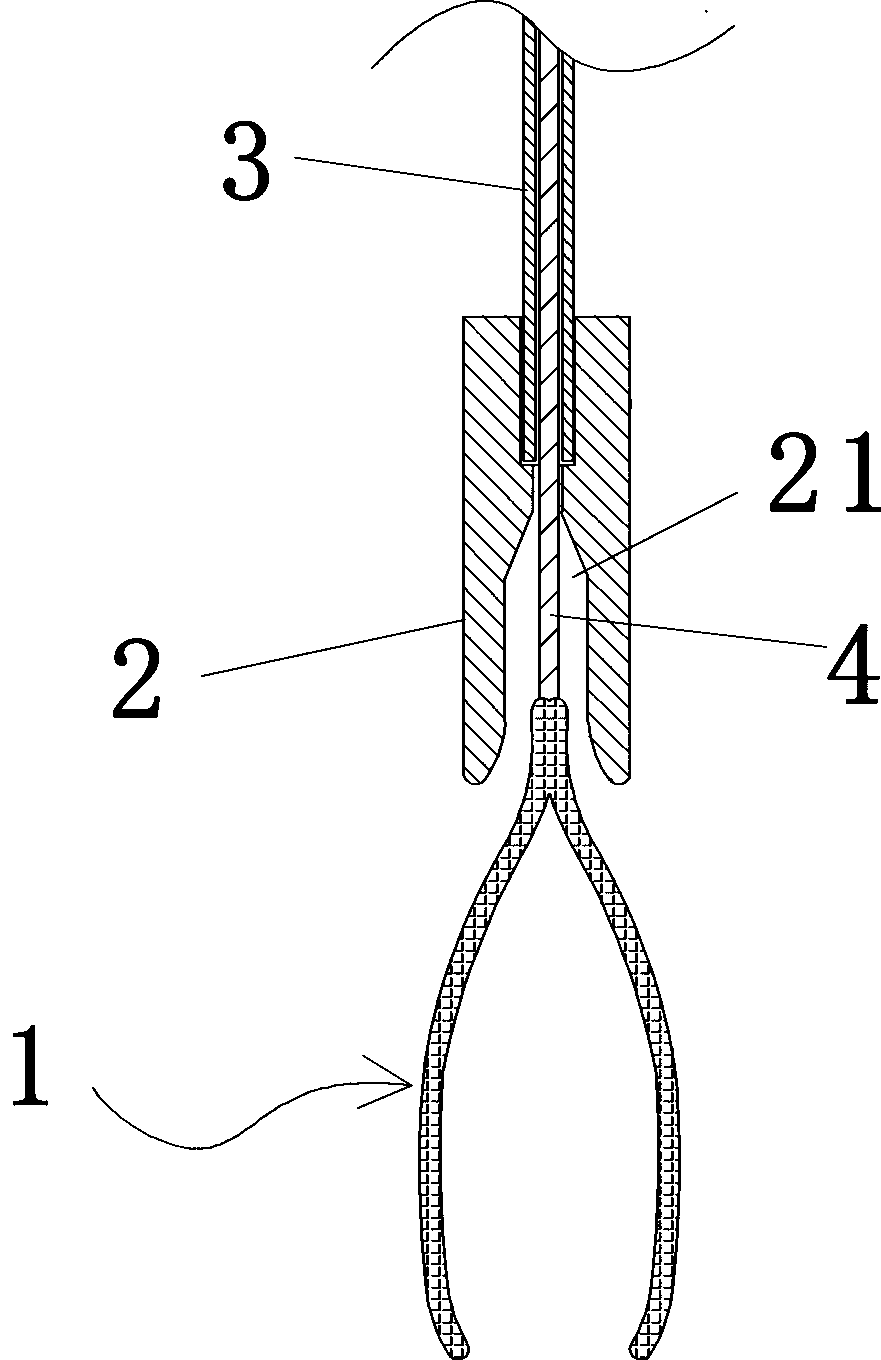
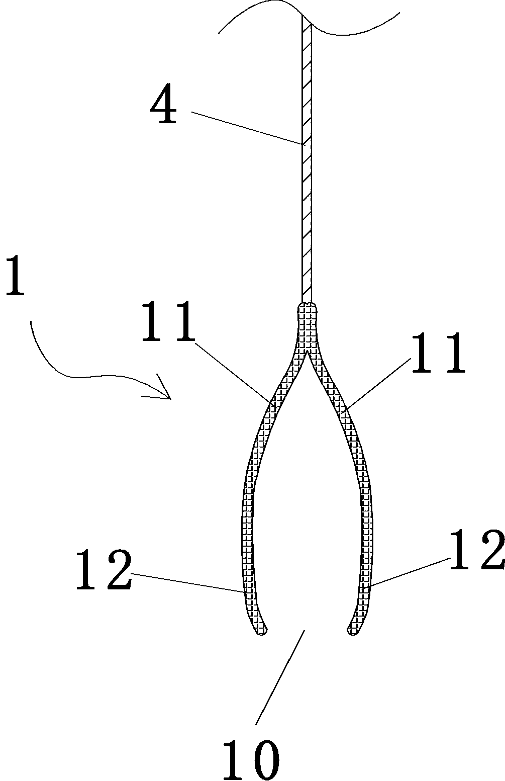
Abdominal minimally invasive surgery clamp
A minimally invasive surgery and jig technology, applied in the fields of surgery, small surgical forceps, medical science, etc., can solve the problems of impossible disassembly and separation or temporary assembly by doctors, and achieve the effect of simple operation and large clamping force.
- Summary
- Abstract
- Description
- Claims
- Application Information
AI Technical Summary
Problems solved by technology
Method used
Image
Examples
Embodiment 2
[0072] The elastic clamp body 1 of this embodiment two is a kind of clamp, and when its metal wire 4 is in relaxed state (normal state), its jaw 10 is opened, as Figure 17 As shown; when the metal wire 4 is pulled upwards, the jaw 10 is closed, and the closed state is as Figure 16 As shown, the rest of the structure of the second embodiment is the same as that of the first embodiment.
Embodiment 3
[0074] The elastic clamp body 1 of the third embodiment is a clamp with a normally closed jaw, which includes two elastic clamp arms 11, each elastic clamp arm 11 includes a clamp arm rear section 111 and a clamp arm front section 112, and the clamp arm The front section 112 is connected to the clamping part 12, and the rear sections 111 of the two clamp arms are connected together in a figure-eight shape. The front sections 112 of the two clamp arms form a cross structure. Under normal conditions, the rear sections 111 of the two elastic clamp arms are naturally opened and Keep the jaw between the two clamping parts 12 in a closed state, such as Figure 18 As shown; when the clamp arm rear section 111 of the two elastic force clamp arms was pressed by the taper of the front end of the clamp body accommodation section 21 and gathered, the jaw between the two clamping parts 12 opened, as Figure 19 shown.
[0075] The structure of other aspects is the same as that of Embodimen...
Embodiment 4
[0078] The difference between the fourth embodiment and the first embodiment mainly lies in the difference of the pressing components. In the fourth embodiment, instead of the tightening bolt 63 , the tightening member adopts a cam mechanism, and the rotation angle of the cam 9 is controlled by the handle 91 . When the high point of the cam 9 was aligned with the wire 4, the cam 9 pressed the wire on the hole wall of the small hole for threading the wire, so that the wire 4 could not move relative to the wire locking member 6, as Figure 21 As shown; when the low point of the cam 9 is aligned with the wire 4, the cam 9 leaves the wire and the wire is relaxed, as Figure 22 shown. The structure of the fourth embodiment is the same as that of the first embodiment.
PUM
 Abstract
Description
Claims
Application Information
 - R&D
- Intellectual Property
- Life Sciences
- Materials
- Tech Scout
- Unparalleled Data Quality
- Higher Quality Content
- 60% Fewer Hallucinations
Browse by: Latest US Patents, China's latest patents, Technical Efficacy Thesaurus, Application Domain, Technology Topic, Popular Technical Reports.
© 2025 PatSnap. All rights reserved.Legal|Privacy policy|Modern Slavery Act Transparency Statement|Sitemap|About US| Contact US: help@patsnap.com


