Simple device and method for dynamically measuring shaking of rotating electrode bar

A rotating electrode and dynamic measurement technology, applied in the field of powder metallurgy industry, can solve the problems affecting the quality of atomized powder, the difficulty of accurate and stable bar operation, and the stability of molten pool affecting the safety of equipment operation, etc., so as to achieve convenient judgment and facilitate quantification The effect of the analysis

Active Publication Date: 2018-06-01
SINO EURO MATERIALS TECH OF XIAN CO LTD
View PDF8 Cites 3 Cited by
  • Summary
  • Abstract
  • Description
  • Claims
  • Application Information

AI Technical Summary

Problems solved by technology

In the actual operation of the bar, in addition to being affected by the original processing state, it also bears the influence of the thermal stress of the plasma gun, internal defects and surface defects, and other mechanical vibrations, so it is difficult to run the bar accurately and stably
When the bar is running unstable, it will affect the safety of equipment operation and the stability of the molten pool, and affect the quality of atomized powder

Method used


Image

  • Simple device and method for dynamically measuring shaking of rotating electrode bar
  • Simple device and method for dynamically measuring shaking of rotating electrode bar
  • Simple device and method for dynamically measuring shaking of rotating electrode bar

Examples


Embodiment 1

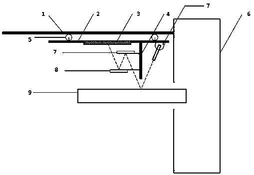
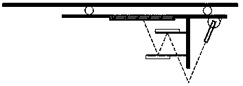
[0055] Use a qualified Ti6Al4V bar with a diameter of 54.98mm, adjust the optical path to meet the requirements of the upper reflector, the lower reflector, and the observation glass parallel to the axis of the bar, and keep the angle between the optical path of the laser transmitter and the vertical line at 30° (or the included angle is 30°), the measured straightness of the bar, and the runout of the outer circle in the middle is 0.022mm. Rotate at 24000rpm, and the diameter of the observation window circle is 22mm after calibration. The bar starts to jump, and the transient state of the bar rising is as follows: Figure 5 As shown, the light spot moves to the right of the observation glass circle, and the transient state of the bar sinking is as follows Figure 6 As shown, the spot moves to the left of the viewing glass circle. Rotate at 30000rpm, calibrate the diameter of the observed glass circle to be 30mm, and find that the bar is still rotating stably. Do not change ...

Embodiment 2

[0057] Use a qualified 304 stainless steel bar with a diameter of 78.90mm, adjust the optical path to meet the requirements of the upper reflector, the lower reflector, and the observation glass parallel to the axis of the bar, and keep the angle between the optical path of the laser transmitter and the vertical line at 50°. The straightness of the bar is measured, and the outer circle in the middle runs out of 0.025mm. Rotate at 20000rpm, and the diameter of the observation window circle is calibrated to 34mm. The bar starts to jump, and the transient state of the bar rising is as follows: Figure 5 As shown, the light spot moves to the right of the observation glass circle, and the transient state of the bar sinking is as follows Figure 6 As shown, the spot moves to the left of the viewing glass circle. Without changing the geometric parameters, replace the second unknown bar, and increase the rotation speed to 20,000rpm. It is observed that the diameter of the spot track ...

Embodiment 3

[0059] Use a qualified TA15 rod with a diameter of 75.12mm, adjust the optical path to meet the requirements of the upper reflector, the lower reflector, and the observation glass parallel to the axis of the bar, and keep the angle between the optical path of the laser transmitter and the vertical line at 80°. The straightness of the bar is measured, and the outer circle in the middle runs out 0.020mm. Rotate at 18000rpm, and the diameter of the observation window circle is 26mm after calibration. The bar starts to jump, and the transient state of the bar rising is as follows: Figure 5 As shown, the light spot moves to the right of the observation glass circle, and the transient state of the bar sinking is as follows Figure 6 As shown, the spot moves to the left of the viewing glass circle. Without changing the geometric parameters, replace the second unknown bar, and increase the rotation speed to 18000rpm. It is observed that the diameter of the spot track circle of the o...


PUM


Abstract

The invention discloses a simple device for dynamically measuring shaking of a rotating electrode bar. The device comprises a guide rail top plate fixed to a furnace wall, transparent glass and a sliding groove rail are arranged on the guide rail top plate, a support is hung below the guide rail top plate through wheels, observation glass marked with concentric circle scales is embedded on the support, a shading plate is arranged on the bottom face of the support, and is provided with an upper reflection mirror face and a lower reflection mirror face, the mirror face body of the upper reflection mirror face faces downwards, the mirror face body of the lower reflection mirror face faces upwards, the centers of the upper reflection mirror face and the lower reflection mirror face are staggered, the two mirror faces are perpendicular to the shading plate, and the shading plate is perpendicular to a support panel; the upper reflection mirror face and the lower reflection mirror face are parallel to the round observation glass, a laser emitter with the adjustable angle is arranged on the right side of the shading plate. Through the device, the running state of the bar can be conveniently and rapidly judged, the bar running state can be precisely subject to quantitative recording, whether running of a certain degree is safe or not is judged through actual operation, and according tothe size of detected light spot track, safe running process parameters can be determined.

Description

technical field [0001] The invention belongs to the technical field of powder metallurgy industry, and in particular relates to a method for measuring the rotation stability of a raw material rod used in a plasma rotating electrode atomization pulverization method. Background technique [0002] The plasma rotating electrode atomization method is a kind of centrifugal atomization technology, and it is also the most popular commercial centrifugal atomization technology. Compared with gas atomization and water atomization methods, the atomization principle of the centrifugal atomization method is based on the inertial force overcoming the surface tension, so it is easy to prepare powders with excellent sphericity and shape regularity. In addition to inheriting the high sphericity characteristics of the centrifugal atomization method, the plasma rotating electrode method has very few impurities because the process does not contact the crucible, and the composition stability afte...

Claims


Application Information

Patent Timeline
Patent Type & Authority Applications(China)
IPC IPC(8): B22F9/10
CPCB22F9/10
Inventor 刘洋韩志宇闫飞陈小林王庆相梁书锦
Owner SINO EURO MATERIALS TECH OF XIAN CO LTD
Why Eureka
Try Eureka