Medical waste treatment device and manufacturing method thereof

A technology for processing equipment and medical waste, which is applied in the field of medical waste processing equipment and its manufacturing, and can solve the problems of complex mold structure, design difficulty, and complex structure design.

Inactive Publication Date: 2018-06-01
乌鲁木齐九品芝麻信息科技有限公司
View PDF6 Cites 4 Cited by
  • Summary
  • Abstract
  • Description
  • Claims
  • Application Information

AI Technical Summary

Problems solved by technology

However, the production of medical and pharmaceutical equipment parts, especially plastic parts, not only has high requirements in terms of material performance, but also has more functional requirements in terms of structure and form. Therefore, plastic part

Method used


Image

  • Medical waste treatment device and manufacturing method thereof
  • Medical waste treatment device and manufacturing method thereof
  • Medical waste treatment device and manufacturing method thereof

Examples


Embodiment Construction

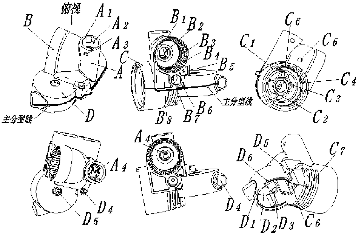
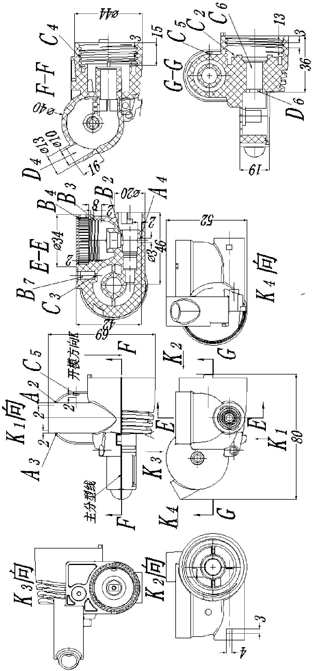
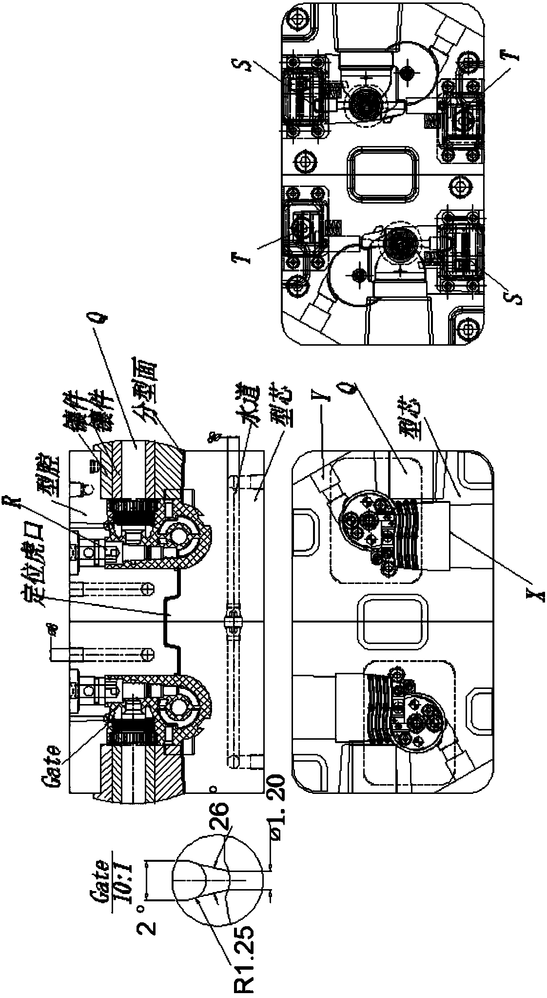
[0047] Figure 1-19 Shown is the relevant explanatory diagram of the present invention; the three-dimensional display diagram of different orientations of the product structure of the object pump body cover targeted by this mold is as follows figure 1 shown. The product is a thin shell, with an average wall thickness of 1.8mm, and the material is modified ABS+PC; the composition of the product is composed of four parts: liquid medicine inlet A, first outlet B, second outlet C, and third outlet D; Product classification design, in figure 1Under the parting of the main parting line designed in , the mold release design of the product is the difficulty in the mold structure design of this product. These difficulties are as follows: A2 is designed on the basis of the cylindrical shell feature A1 of the liquid inlet A feature , A3, and A4 are three features that affect the demoulding of the product. A2, A3 are the side holes on the A1 cylinder, and A4 is a circular groove on th...


PUM


Abstract

The invention provides a medical waste treatment device and a manufacturing method thereof. A gating system is a cold runner point pointed gate pouring manner, single-point feeding is achieved, in order to shorten the length of the runner and ensure the injection molding liquidity of a material flow, a flange type positioning ring flange sleeve is adopted in a gate sleeve, a phi8mm round runner isadopted in a horizontal runner on a flowing plate in the runner system, a pointed gate sleeve independent embedding manner is adopted in a vertical runner penetrating a fixed mold plate, and the gatewater inlet diameter is phi1.2mm.

Description

technical field [0001] The invention relates to the field of medical device design, in particular to medical waste treatment equipment and a manufacturing method thereof. Background technique [0002] Medical waste treatment equipment in the prior art, see appendix Figure 20 , comprising a frame 100, the frame 100 is provided with a crushing box 200, a drive motor 300 and a bearing seat 400; the bottom of the crushing box 200 is communicated with a secondary crushing device 800 arranged below the frame 100, and the bottom of the secondary crushing device 800 Be communicated with the collection box 1000 that has filter screen 900; Collection box 1000 is connected with ozone generator 110, and secondary pulverization device 800 comprises casing 140 and pulverization motor 150, and the output of pulverization motor 150 is connected with the pulverization shaft that stretches in casing 140 160, the outer surface of the crushing shaft 160 is spirally provided with a crushing bla...

Claims


Application Information

Patent Timeline
IPC IPC(8): B29C45/26B29C45/33B29C45/27B29L31/00
CPCB29C45/26B29C45/2602B29C45/2708B29C45/33B29C45/332B29C2045/2683B29L2031/753
Inventor 不公告发明人
Owner 乌鲁木齐九品芝麻信息科技有限公司
Why Eureka
Try Eureka