High-speed train wind resistance braking device

A technology for wind resistance braking and high-speed trains, which is applied in the fields of pneumatic brakes, transportation and packaging, railway car body parts, etc. It can solve the problems that cannot meet the braking conditions, do not involve multi-angle locking scheme design, and the oil leakage of hydraulic cylinders is difficult to maintain and other problems, to achieve the effect of fast emergency braking response, light weight, and fast opening speed

Inactive Publication Date: 2018-06-01
NANJING CRRC PUZHEN HAITAI BRAKE EQUIP CO LTD
View PDF10 Cites 14 Cited by
  • Summary
  • Abstract
  • Description
  • Claims
  • Application Information

AI Technical Summary

Problems solved by technology

The two-way wind resistance braking device for high-speed EMUs of the present invention breaks through the traditional thinking and creatively designs a wind resistanc...

Method used


Image

  • High-speed train wind resistance braking device
  • High-speed train wind resistance braking device
  • High-speed train wind resistance braking device

Examples


Embodiment 1

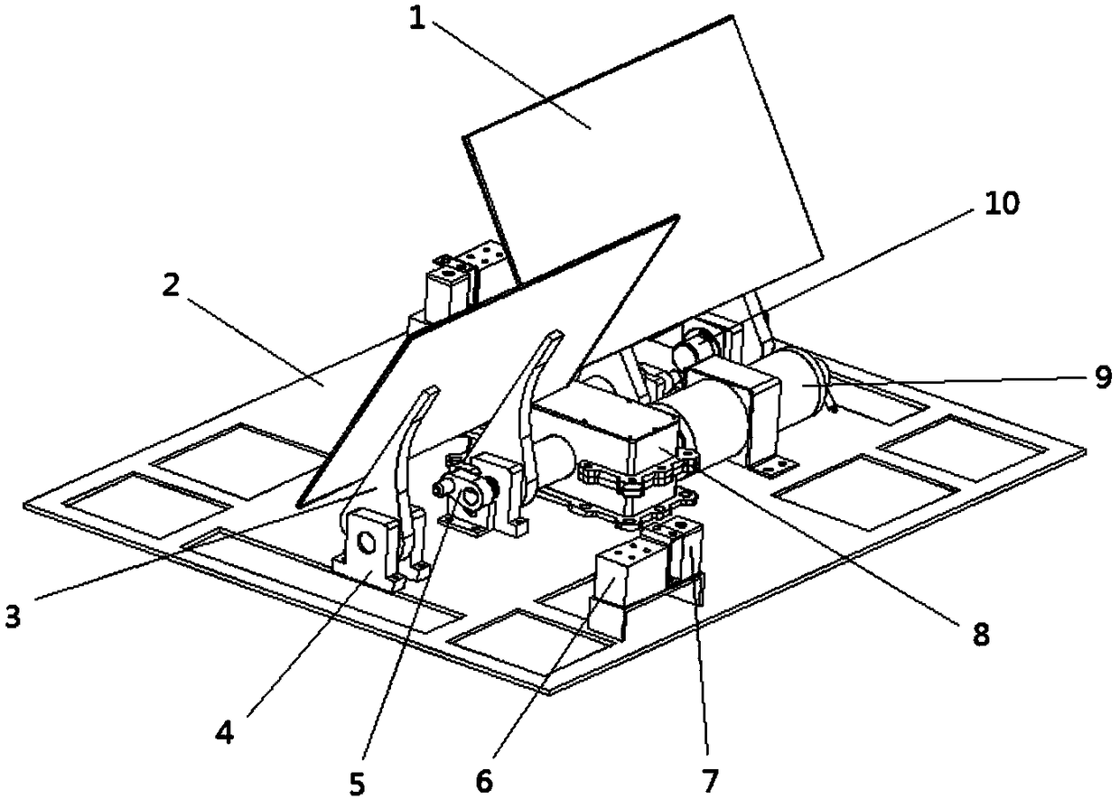
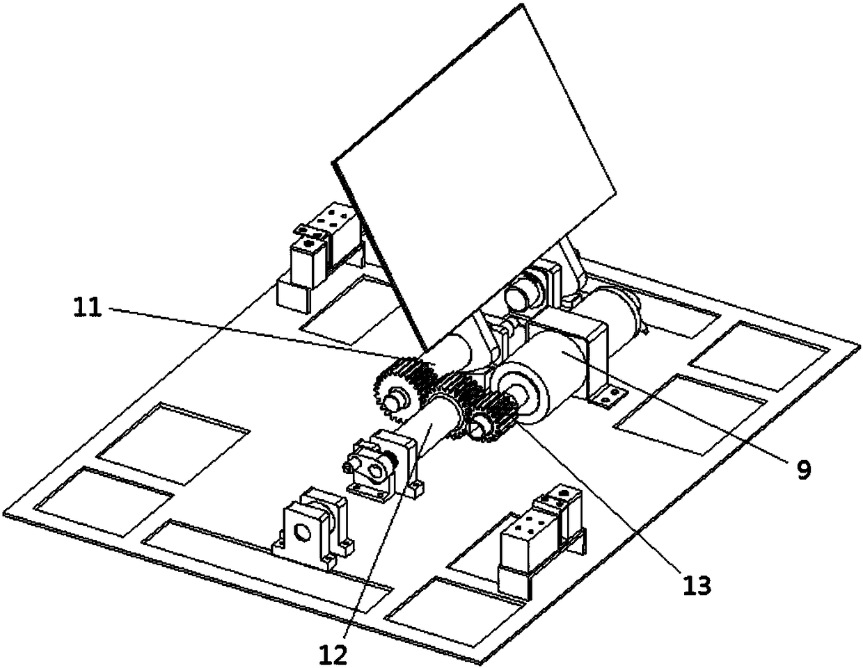
[0024] The common braking working principle of the wind resistance braking device is as follows: when the wind resistance braking device needs to implement normal braking, according to the output signal of the braking system controller, the locking device 6 is unlocked, and the opening mechanism 7 will brake the wind vane 1 Open a small angle, the motor 9 rotates forward, and the transmission gear shafts on both sides drive the brake wind vane 1 to open in the opposite direction; when providing stable normal braking deceleration, according to the output signal of the brake system controller and the angle sensor 10 , the motor 9 stalls, the gear shafts on both sides stop rotating, and the brake wind vane 1 is fixed at an angle, thereby realizing the function of locking the brake wind vane 1 and the bottom plate 2 of the box at any angle within 0-75 degrees.

Embodiment 2

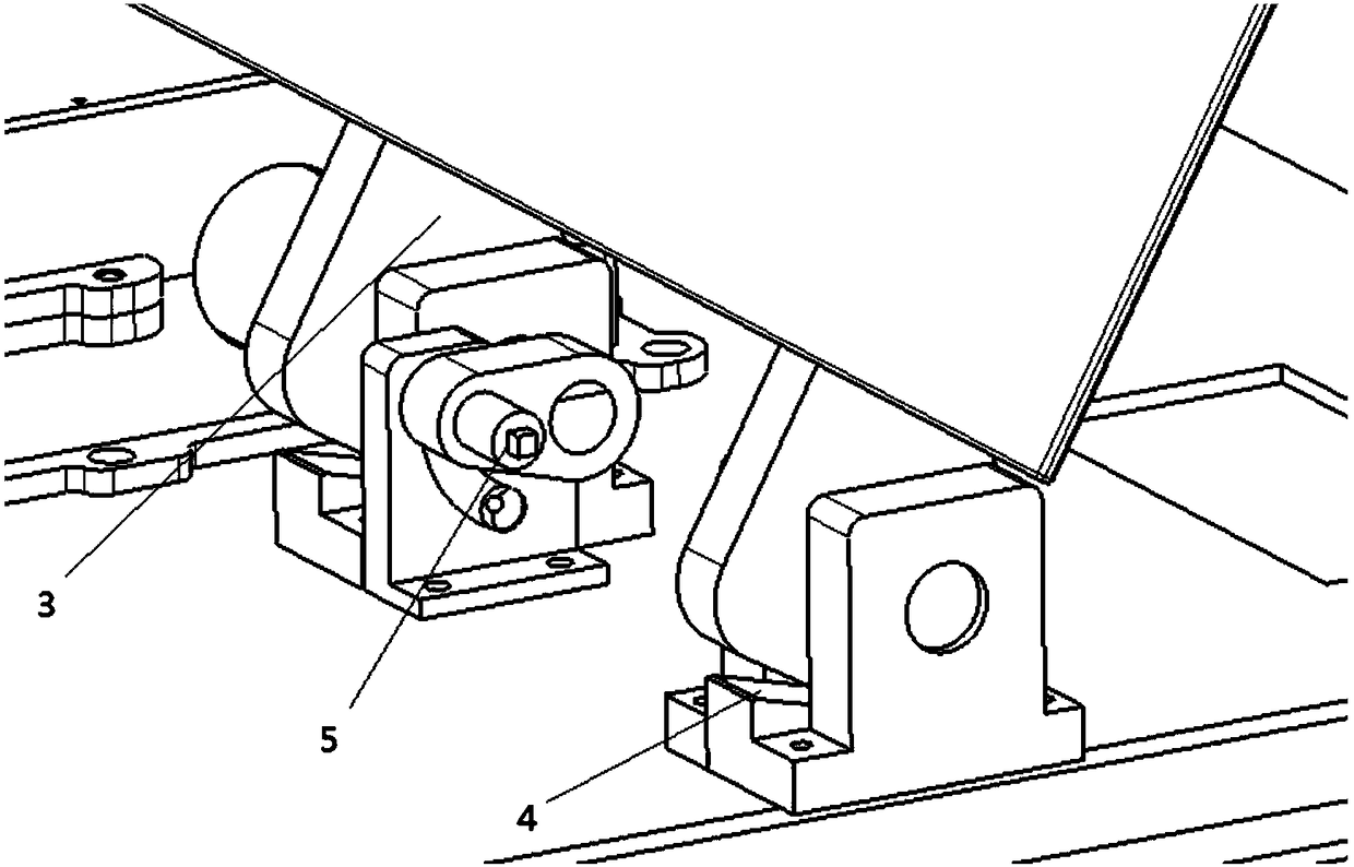
[0026] The emergency braking working principle of the wind resistance braking device is as follows: when the braking system controller outputs a signal or the vehicle loses power, the present invention implements the emergency braking locking device 6 to unlock, and the opening mechanism 7 is triggered to brake the wind vane 1 Open a small angle, drive the brake wind vane 1 to open in the opposite direction by the walking wind, when reaching the maximum angle, the stop part (slope surface) of the stop bearing seat 4 prevents the rocker arm 3 from rotating beyond the maximum angle, and the locking mechanism 5 The rotation angle error is limited to no more than one degree, so under emergency braking conditions, the brake wind vane 1 is directly opened to 75 degrees and locked.

[0027] The recovery working principle of the wind resistance brake device is as follows: when there is no need to brake, the motor 9 reverses, the gear shafts on both sides drive the brake wind vane 1 to ...


PUM


Abstract

The invention discloses a high-speed train wind resistance braking device, which comprises a box fixedly embedded to the top of a train. Opening mechanisms, locking devices, a driving mechanism, a transmission mechanism, a locking mechanism and an angle sensor are arranged in the box. The driving mechanism is connected with the transmission mechanism, upper ends of the opening mechanisms and the locking devices contact with middles of inner surfaces of brake wind wing plates, and the inner surfaces of the brake wind wing plates refer to surfaces, in a roof, of the folded brake wind wing plates. Rocker arms are mounted on retaining bearing seats which are mounted on a bottom plate of the box, the rocker arms rotate based on the retaining bearing seats, the locking mechanism is used for controlling rotation angles of the rocker arms, the brake wind wing plates are mounted on the rocker arms, and the angle sensor is used for measuring rotating angles of the rocker arms. The high-speed train wind resistance braking device is excellent in braking effect and capable of meeting different requirements of service braking and emergency braking states, and a function of locking the brake windwing plates in any angles ranging from 0 to 75 degrees can be realized.

Description

technical field [0001] The invention relates to the field of high-speed train braking, in particular to a high-speed train wind resistance braking device. Background technique [0002] Wind resistance braking as non-adhesive braking is an important supplement to the existing high-speed train braking system. Structural changes are small and wind energy is used, which is environmentally friendly. In Japan, the superconducting maglev train with a target operating speed of 500km / h and the East Japan Railway E954 Shinkansen test vehicle with a target operating speed of 360km / h have loading examples. In China, the wind resistance braking device designed by CSR Qingdao Sifang and Tongji University has also been verified in wind tunnel tests. [0003] The patent "windage braking device and motor car body using the windage braking device" (patent number CN201210460635) describes a windage braking device, including a windage braking plate and a driving mechanism; the driving mechani...

Claims


Application Information

Patent Timeline
IPC IPC(8): B61H11/10
CPCB61H11/10
Inventor 杨俊刘寅虎冯云明马璐贺成田春吴萌岭庄国明孙卫兵翁晶晶
Owner NANJING CRRC PUZHEN HAITAI BRAKE EQUIP CO LTD
Why Eureka
Try Eureka