Automatic lifting device

A lifting device and automatic technology, applied in the field of mechanical control, can solve the problems of heavy workload, electrical devices, casualty devices, and low handling efficiency, and achieve the effects of high safety, reduced labor intensity, and easy lifting operations

Inactive Publication Date: 2018-06-01
HUBEI JINSHIWEI INTELLIGENT EQUIP TECH
View PDF9 Cites 6 Cited by
  • Summary
  • Abstract
  • Description
  • Claims
  • Application Information

AI Technical Summary

Problems solved by technology

[0003] The purpose of the present invention is to provide an automatic lifting device, which solves the problems of low handling efficiency, heavy workload of personnel, and easy fall of electrical devices during the handling of existing large electrical devices, causing casualties and device damage. The problem

Method used


Image

  • Automatic lifting device
  • Automatic lifting device
  • Automatic lifting device

Examples


Embodiment Construction

[0035] The following will clearly and completely describe the technical solutions in the embodiments of the present invention with reference to the accompanying drawings in the embodiments of the present invention. Obviously, the described embodiments are only some, not all, embodiments of the present invention. Based on the embodiments of the present invention, all other embodiments obtained by persons of ordinary skill in the art without creative efforts fall within the protection scope of the present invention.

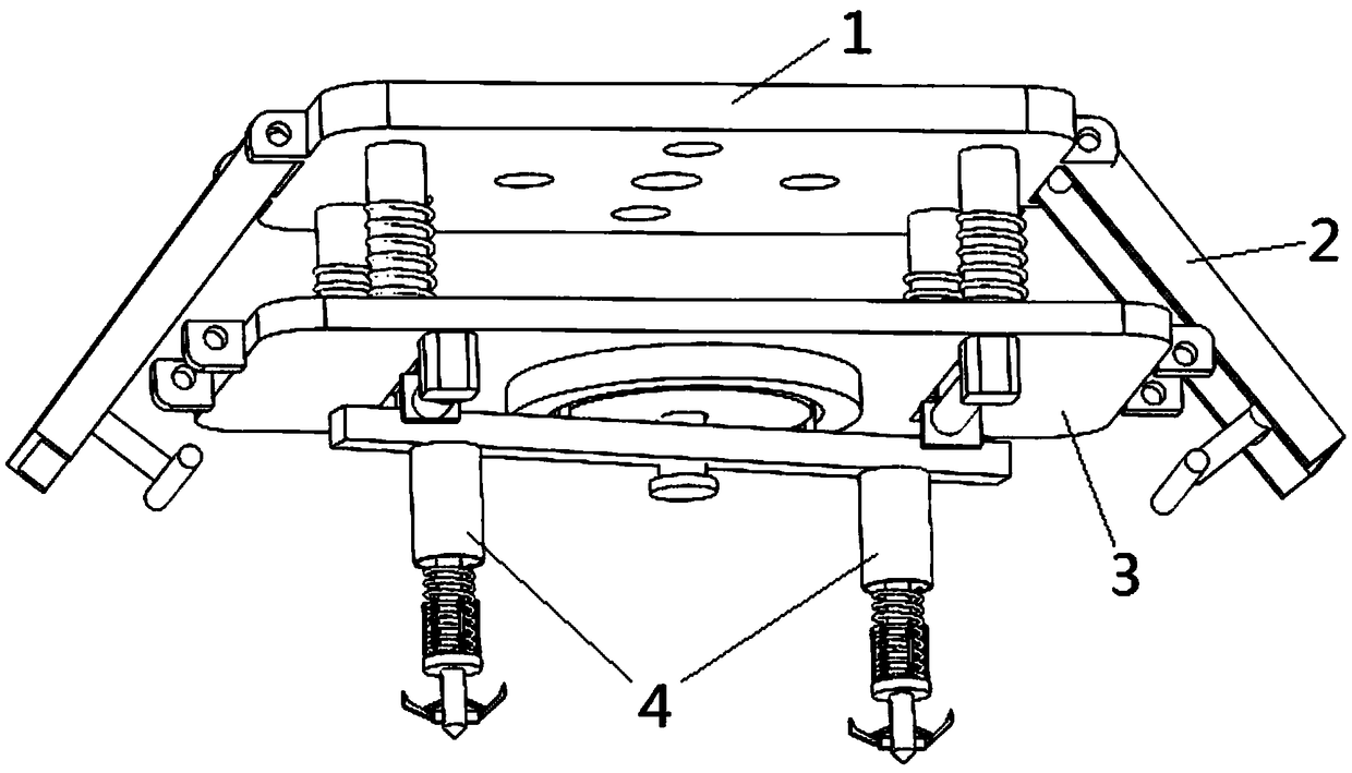
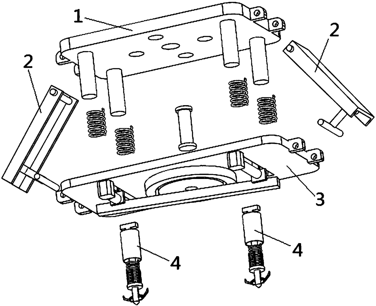
[0036] see Figure 1-7 As shown, the present invention is an automatic lifting device, including a connecting top seat 1, a connecting mechanism 2, a steering adjustment mechanism 3 and a lifting mechanism 4;

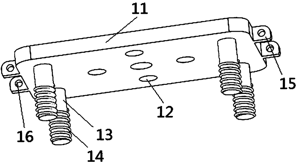
[0037] The connecting top base 1 includes a top plate 11, which is provided with a number of fixing holes 12 for fixing the lifting device; four symmetrically distributed telescopic rods 13 are installed on the lower surface of the top plate 11, and buffer s...


PUM


Abstract

The invention discloses an automatic lifting device. The automatic lifting device comprises a connecting top base, a connecting mechanism, a steering adjustment mechanism and a lifting mechanism; theconnecting top base comprises a top plate and an extension rod; the top plate is connected with the steering adjustment mechanism through the extension rod; a first lifting ring is mounted on the topplate; the steering adjustment mechanism comprises a mounting plate and a rotary adjusting plate; a second lifting ring is arranged on the mounting plate; a motor, an electric extension rod and a slide block are mounted on the mounting plate; the motor is connected with the slide block through the electric extension rod; a circular rail is formed in the rotary adjusting plate; a clamping block ismounted in the circular rail; a rotating plate is fixed on the clamping block, and is provided with a mounting groove; the connecting mechanism is connected with lifting rings for connecting the top base with the steering adjustment mechanism; and the lifting mechanism comprises a support device and a hanging hook device. Through mechanism design of the lifting device, lifting of electric appliances in different placing positions can be realized; and the automatic lifting device has the characteristics of high working efficiency, high safety, convenience to operate and high stability, and greatly reduces both manpower and material resources.

Description

technical field [0001] The invention belongs to the technical field of mechanical control and relates to an automatic lifting device. Background technique [0002] With the continuous development of industry, electrical devices are indispensable devices in industrial production. Many components are integrated in electrical devices, and industrial control can be realized through the connection between components. At present, the structure of industrial electrical devices is relatively large. , There is a lifting ring on the top of the electrical device for lifting. At present, in the process of lifting and handling, through the combination of manual or lifting operation, the problem of falling is prone to occur during the lifting process, causing casualties. And it is easy to cause damage to the electrical device, which not only increases the workload of personnel, but also reduces the efficiency of handling. Contents of the invention [0003] The purpose of the present in...

Claims


Application Information

Patent Timeline
Patent Type & Authority Applications(China)
IPC IPC(8): B66C1/22B66C1/34
CPCB66C1/22B66C1/34
Inventor 任磊
Owner HUBEI JINSHIWEI INTELLIGENT EQUIP TECH
Why Eureka
Try Eureka