Lifting mechanism

A technology of lifting mechanism and wire reel, which is applied in the direction of clockwork mechanism and hoisting device, can solve the problems of unfavorable installation and control, damage of motor, influence on transmission reliability, etc., and achieve the effect of convenient control

Pending Publication Date: 2018-06-01
赖季谷
View PDF0 Cites 1 Cited by
  • Summary
  • Abstract
  • Description
  • Claims
  • Application Information

AI Technical Summary

Problems solved by technology

[0003] When the lifting mechanism of the prior art drives the lifting object to move up and down, taking downward as an example, it may encounter obstacles during the descent process, thereby affecting the normal operation of the lifting mechanism. At this time, if the motor continues to rotate, it may cause damage
In addition, in the prior art, in order to control the up and down travel of the lifting mechanism, an up and down travel switch is provided. However, in the prior art, the travel switch is often set on the frame at the end of the travel of the up and down motion track, so that it is necessary to lift objects to collide with the travel switch. , is not conducive to installation and control
Someone proposed to install the limit switch on the tail shaft of the motor reducer. This design needs to expose the tail shaft of the reducer, which affects the transmission reliability.

Method used


Image

  • Lifting mechanism
  • Lifting mechanism
  • Lifting mechanism

Examples


Embodiment Construction

[0020] The present invention will be further described below in conjunction with the accompanying drawings and specific embodiments.

[0021] The present invention covers any alternatives, modifications, equivalent methods and schemes made on the spirit and scope of the present invention. In order to provide the public with a thorough understanding of the present invention, specific details are set forth in the following preferred embodiments of the present invention, but those skilled in the art can fully understand the present invention without the description of these details. In addition, for the sake of illustration, the drawings of the present invention are not completely drawn according to the actual scale, and are described here.

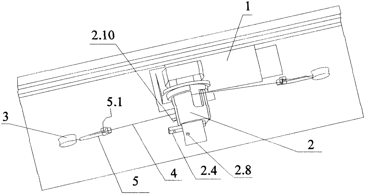
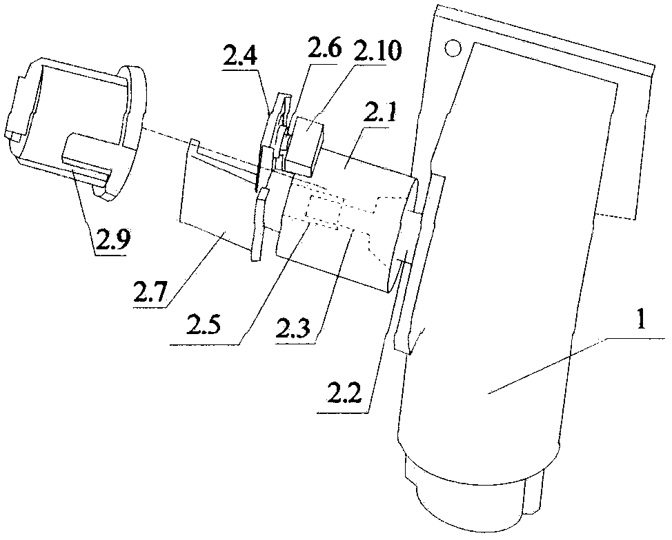
[0022] Such as figure 1 and 2 As shown, the lifting mechanism of the present invention includes a motor 1, a wire reel 2 and two pulleys 3, and the motor 1 drives the wire reel 2 to rotate, and the stay cord 4 on the wire reel 2 is respect...


PUM


Abstract

The invention discloses a lifting mechanism. The lifting mechanism comprises a motor (1), a winding device (2) and two pulleys (3), the winding device (2) is driven to rotate through the motor (1), digging ropes (4) on the winding device (2) are arranged on the two pulleys (3) in an extending mode, and the digging ropes (4) are connected to the two ends of a lifting object through the two pulleys(3); a rebound switch (5) is arranged between the winding device (2) and the at least one pulley (3); the digging ropes (4) are clamped into clamping grooves (5.1) in the rebound switch (5); and the rebound switch (5) is electrically connected with a controller for controlling a working state of the motor (1). According to the lifting mechanism, in the falling process of the lifting object, by designing the rebound switch, when the lifting mechanism encounters foreign matter, the rebound switch is bounded up, and the motor is controlled to stop working through the controller; and meanwhile, the structure of the winding device is skillfully designed, so that a stroke switch is controlled through a structure on the winding device.

Description

technical field [0001] The invention relates to the technical field of lifting devices, in particular to a lifting mechanism. Background technique [0002] Lifting mechanisms are widely used in people's production and life, such as elevators, and so on. With the development of smart home, the lifting mechanism is also used in kitchen and bathroom and household fields. Taking the lifting mechanism used for kitchen and bathroom as an example, the lifting mechanism in the prior art usually includes a motor, a wire reel and pulleys on both sides. The device rotates, and the stay rope on the wire reel extends to the pulleys on both sides respectively, and is connected with the lifting object of the lifting mechanism. [0003] When the lifting mechanism in the prior art drives the lifting object to move up and down, taking downward as an example, it may encounter obstacles during the downward process, thereby affecting the normal operation of the lifting mechanism. At this time,...

Claims


Application Information

Patent Timeline
Patent Type & Authority Applications(China)
IPC IPC(8): B66D1/12B66D1/30
CPCB66D1/12B66D1/30
Inventor 赖季谷
Owner 赖季谷
Why Eureka
Try Eureka