
Movable step slope cushion

A mobile, stepped technology, applied in the direction of roads, special pavements, roads, etc., can solve problems such as the bottom of the vehicle hitting the slope pad or platform, reducing the speed of road traffic, and the vehicle suddenly turning, reducing friction and improving connection. Fixed effect, power-reducing effect

Active Publication Date: 2018-06-01
郑州靓岛建筑设计有限公司
View PDF5 Cites 2 Cited by
  • Summary
  • Abstract
  • Description
  • Claims
  • Application Information

AI Technical Summary

Problems solved by technology

For the safety of pedestrians, a platform for pedestrians is often set up on both sides of the road, and a stepped structure is formed between the platform and the road. Larger, after repeated rolling, the part of the platform close to the side of the road is prone to collapse, affecting pedestrians' walking, and easily causing dangers such as falls. Repeated construction and repairs are required, resulting in waste of funds
In order to solve this problem, people often set up fixed slope pads between the flat ground and the road. The fixed slope pads will have a great impact on road traffic, especially in narrower street roads. The place must slow down, and the unilateral wheel passes slowly on the slope pad, otherwise it is easy to cause great damage to the tire, and it is prone to dangerous situations such as the bottom of the vehicle hitting the slope pad or platform or the vehicle turning suddenly, and it is easy to reduce the speed of the entire road traffic , and where there are slope pads, it is inconvenient for bicycles and electric vehicles to pass through, and they need to go around, and it is easy to cause traffic accidents such as scratches with the vehicles next to them, and it is easy to cause traffic jams

Method used


Image

  • Movable step slope cushion
  • Movable step slope cushion
  • Movable step slope cushion

Examples


Embodiment

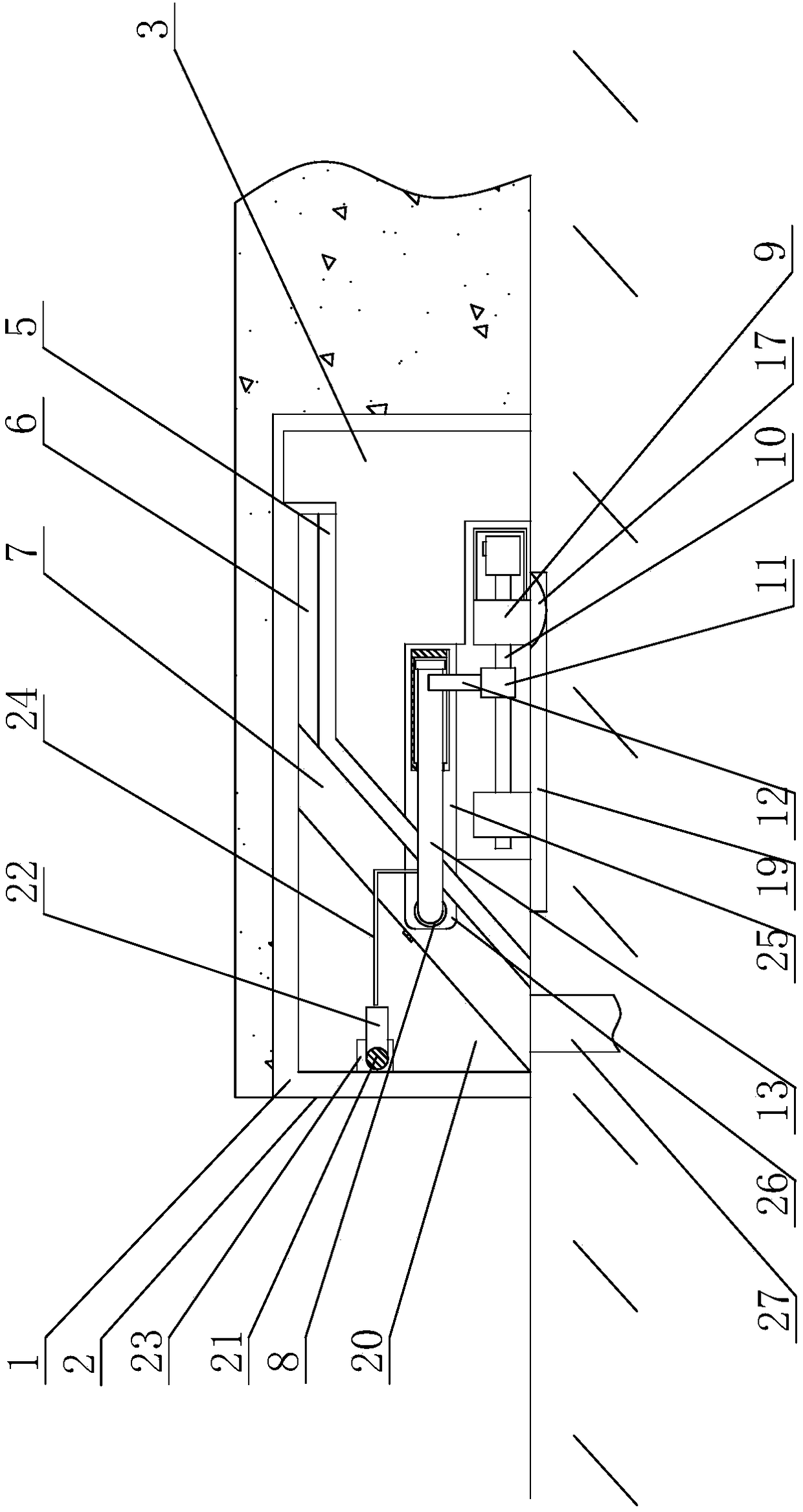
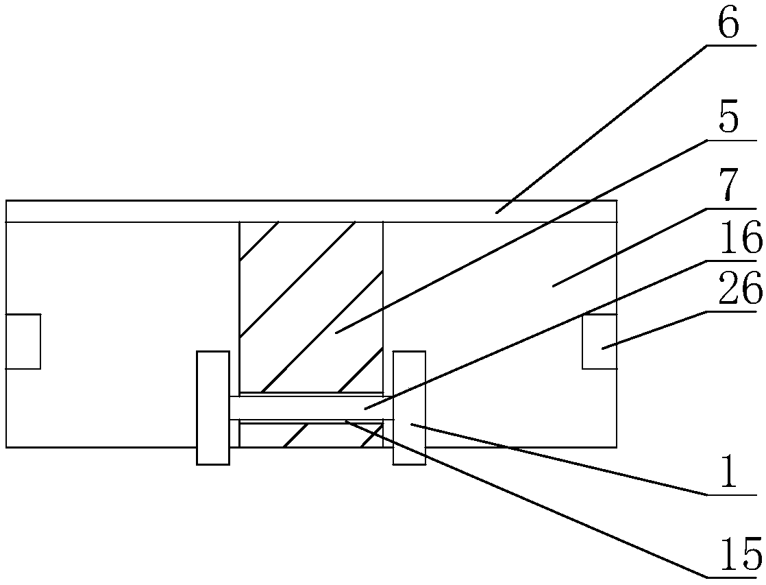
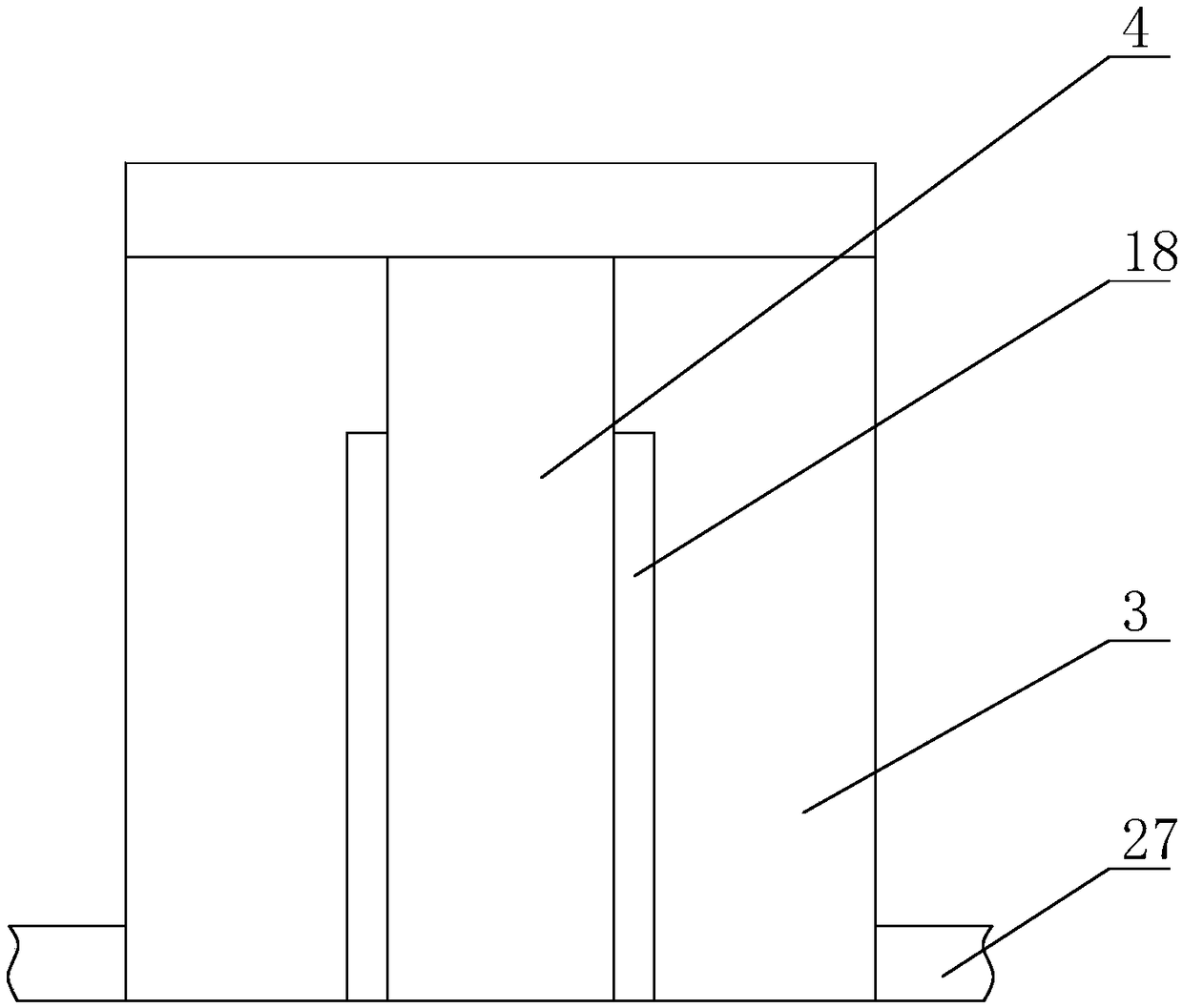
[0043] A movable step slope pad, comprising a housing chamber 1 arranged below the platform, the bottom of the housing chamber 1 near the opening of the platform is provided with a drainage ditch 27, the drainage ditch is connected to an underground drainage device, the housing chamber 1 One end close to the edge of the platform is provided with an entrance and exit 2, and a fixed block 3 is provided in the accommodating cavity 1, and the fixed block is used to provide a moving support point and a moving track for the movable sliding block, and the middle part of the fixed block 3 is vertical A moving groove 4 is provided, an opening is provided at one end of the moving groove 4 near the entrance and exit 2, a sliding block 5 adapted to the moving groove 4 is slidably provided in the moving groove 4, and a passageway is arranged on the sliding block 5. hole 15, the through hole 15 is pierced with a rotating shaft 16, the two ends of the rotating shaft 16 exposed outside the thr...


PUM


Abstract

The invention discloses a movable step slope cushion and mainly relates to the field of civil engineering. The movable step slope cushion comprises a storage cavity and a moving device, wherein a doorway is arranged at one end of the storage cavity; a fixed block is arranged in the storage cavity and provided with a moving groove; an opening is formed in the end, close to the doorway, of the moving groove; a slider is glidingly arranged in the moving groove; a flat plate is arranged at the upper end of the slider; a slope plate is obliquely arranged at the outer end of the slider; positioningholes are formed in two ends of the slope plate; the moving device comprises two support blocks, a screw is arranged between the two support blocks, a drive motor is arranged at one end of the screw,a nut is arranged on the screw, an L-shaped connecting rod is arranged on the nut, a moving rod is arranged at a horizontal end of the connecting rod, and a positioning rod is arranged at one end of the moving rod and can be placed into the positioning holes. The movable step slope cushion has the following beneficial effects: problems in the prior art can be solved as many as possible, roller compaction on the platform edge is reduced, traffic hindering is avoided, the platform is protected, the service life is prolonged, capital destruction is reduced, and passage effect can be improved.

Description

technical field [0001] The invention relates to the field of civil engineering, in particular to a movable step slope pad. Background technique [0002] Civil engineering is a general term for the science and technology of building various engineering facilities. It not only refers to the applied materials, equipment and technical activities such as survey, design, construction, maintenance and repair, but also refers to the object of engineering construction, that is, the construction on the ground or underground, on land or in water, directly or indirectly for human beings. Service in all aspects. For the safety of pedestrians, a platform for pedestrians is often set up on both sides of the road, and a stepped structure is formed between the platform and the road. Larger, after repeated rolling, the part of the platform close to the side of the road is prone to collapse, affecting pedestrians' walking, and easily causing dangers such as falls. Repeated construction and r...

Claims


Application Information

Patent Timeline
Patent Type & Authority Applications(China)
IPC IPC(8): E01C9/08
Inventor 任索影李亮李广慧
Owner 郑州靓岛建筑设计有限公司
Learn More