Original-soil and in-situ slurrying-based underground wall construction method

A construction method and in-situ system technology, applied in the direction of foundation structure engineering, sheet pile walls, buildings, etc., can solve the problems of lower project cost, rough walls, high requirements, etc., to improve project safety, reduce processing costs, enhance The effect of compressive properties

Active Publication Date: 2018-06-01
章胜南 +2
View PDF4 Cites 3 Cited by
  • Summary
  • Abstract
  • Description
  • Claims
  • Application Information

AI Technical Summary

Problems solved by technology

[0004] Now there is another construction method is the cast-in-place underground continuous wall. First, use a slotting machine to make a groove in the ground, and then put a reinforcement cage in the mud, insert a pouring pipe into the mud, and pour it at the bottom of the groove through high pressure. The pouring pipe is moved up after each pouring until the entire wall is poured. The wall made by this construction method is not only used as a temporary support structure for the foundation pit, but also as a permanent outer wall of the basement, which greatly reduces the engineering cost. cost, but the construction method of the underground diaphragm wall also has many disadvantages: (1) Since the concrete is directly poured in the mud, the mud requirements are high, and the soil in the groove needs to be taken out and then added with various additives for slurrying. Then the mud is introduced into the groove, and finally t

Method used


Image

  • Original-soil and in-situ slurrying-based underground wall construction method
  • Original-soil and in-situ slurrying-based underground wall construction method
  • Original-soil and in-situ slurrying-based underground wall construction method

Examples


Embodiment Construction

[0033] The present invention will be further described below in conjunction with accompanying drawing and specific embodiment:

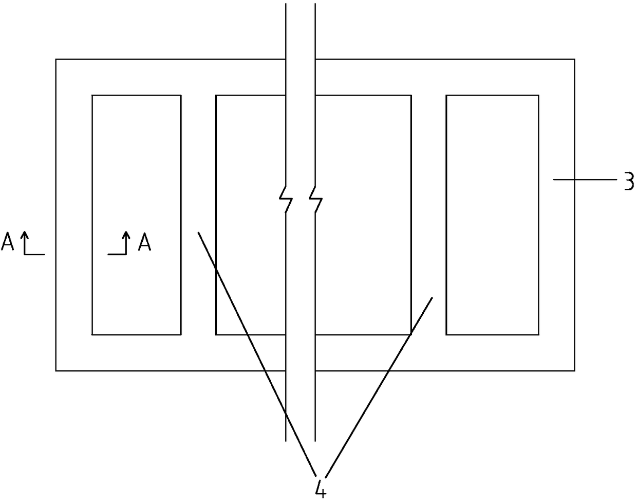
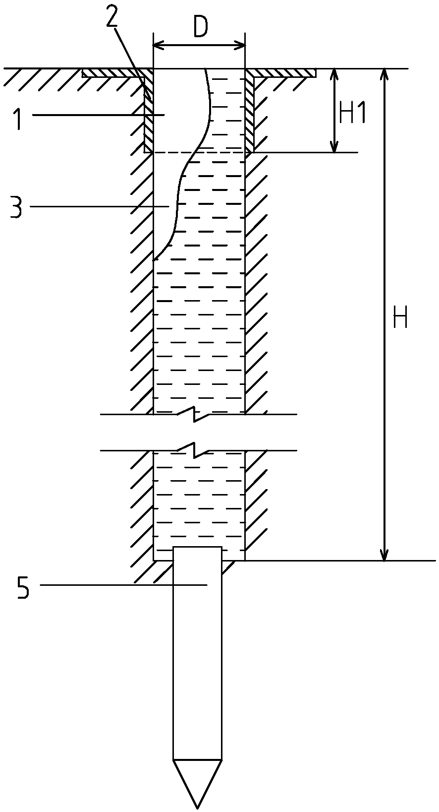
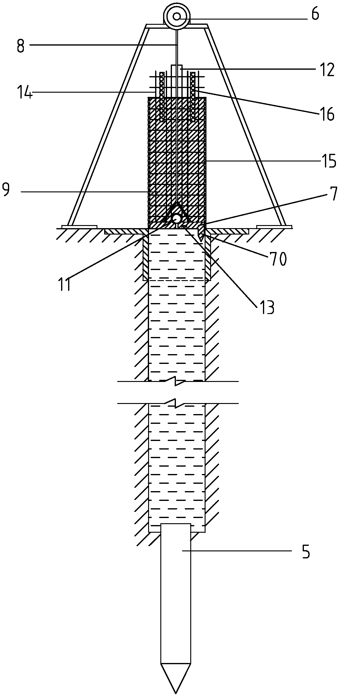
[0034] like figure 1 , figure 2 , image 3 , Figure 4 and Figure 5Shown is a kind of underground wall construction method based on original soil in-situ grouting, comprising the following steps: a, opening a back-shaped mud guide groove 1 with a depth of H1 on the ground, pouring guide wall 2 with concrete, Install the guide wall on both sides of the mud guide groove, open a groove 3 at the bottom of the guide groove through a slotting machine, and open a groove with a predetermined depth H in a back-shaped structure. The depth H1 of the guide groove is the same as the predetermined depth H The ratio is 0.07-0.15, and a plurality of parallel support beam avoidance grooves 4 are opened inside the groove, and the two ends of the support beam avoidance grooves communicate with the inner wall of the groove; b. The pipeline injects water into the ...


PUM

PropertyMeasurementUnit
Densityaaaaaaaaaa

Abstract

The invention relates to the technical field of underground construction and discloses an original-soil and in-situ slurrying-based underground wall construction method. The original-soil and in-situslurrying-based underground wall construction method comprises the following steps of a, performing a grooving process, b, during the grooving process, injecting water into soil via a high-pressure pipe through a grooving machine, then performing stirring to form slurry, performing multi-spot sampling, detecting the density of slurry samples through a slurry densitometer, injecting water to adjustthe density of the slurry, performing sampling and detecting processes until the density of the slurry reaches a required density rho, and c, transversely and monolithically pouring a first wall piece on a support plate, after the first wall piece is formwork-removed, sinking the top surface of the first wall piece through a hoist till being level to the ground, and transversely and monolithically pouring a second wall piece on the first wall piece, wherein the second wall piece and the first wall piece are longitudinally overlapped, and sequentially transversely and monolithically pouring and sinking a plurality of wall pieces and son on in the identical manner until underground wall construction is completed. An underground wall constructed according to the original-soil and in-situ slurrying-based underground wall construction method is high in quality, free from leakage and secondary construction and capable of greatly reducing the construction cost and shortening the constructionperiod.

Description

technical field [0001] The invention relates to the technical field of underground construction, in particular to an underground wall construction method based on in-situ pulping of raw soil. Background technique [0002] With the development of society, urban construction is changing with each passing day, and there are more and more underground projects, such as high-rise building basements, underground corridors, multi-storey underground garages, subway tunnels and other underground construction projects. These projects are all deep foundation construction. In order to ensure the safety of construction and the safety and stability of the surrounding environment, foundation pit enclosure is required. [0003] At present, the foundation pit enclosure usually adopts the scheme of pile row wall plus internal support or pile row wall plus external cable, but the pile row wall is a temporary support structure. The pile wall becomes a permanent waste, which greatly increases th...

Claims


Application Information

Patent Timeline
IPC IPC(8): E02D5/20
Inventor 章胜南吴朝峰孙正东
Owner 章胜南
Why Eureka
Try Eureka