
Automatic device for prevention and treatment of dust in quarry drilling perforation operation

An automation equipment and quarry technology, applied in mining equipment, drilling equipment, dust prevention, etc., can solve the problems of single dust collection direction, low degree of automation, and poor spray effect, so as to improve the dust collection effect and dust reduction effect Effect

Inactive Publication Date: 2018-06-01
潘春燕
View PDF8 Cites 1 Cited by
  • Summary
  • Abstract
  • Description
  • Claims
  • Application Information

AI Technical Summary

Problems solved by technology

[0004] In order to solve the above problems, the present invention provides an automatic equipment for dust prevention and treatment in rock drilling and perforation operations in quarries, which can solve the problem of manual spraying and manual adjustment in the existing down-the-hole drilling rigs in rock drilling and perforation. Spray angle, complex operation, low degree of automation, poor spray effect, fixed method of vacuuming, single direction of vacuuming, slow vacuuming speed and poor vacuuming effect, etc., can simultaneously realize the spray dust suppression when the down-the-hole drilling rig is drilling rock. And automatic dust collection function, with no need for manual adjustment of spray operation, automatic adjustment of spray angle, easy operation, high degree of automation, good spray effect, active dust collection, adjustable dust collection direction, fast dust collection speed and good dust collection effect Etc

Method used


Image

  • Automatic device for prevention and treatment of dust in quarry drilling perforation operation
  • Automatic device for prevention and treatment of dust in quarry drilling perforation operation
  • Automatic device for prevention and treatment of dust in quarry drilling perforation operation

Examples


Embodiment Construction

[0021] In order to make the technical means, creative features, goals and effects achieved by the present invention easy to understand, the present invention will be further described below in conjunction with specific illustrations.

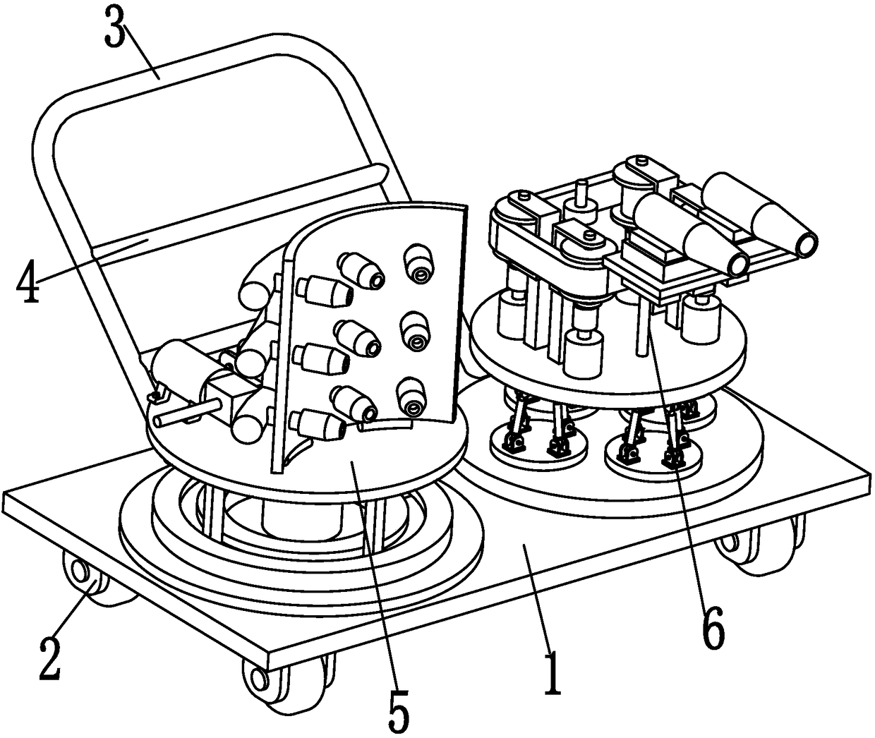
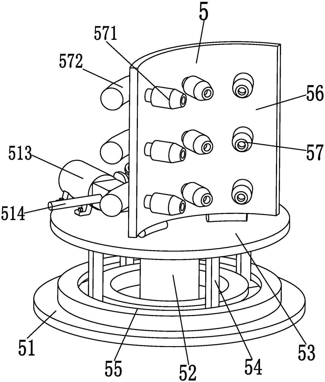
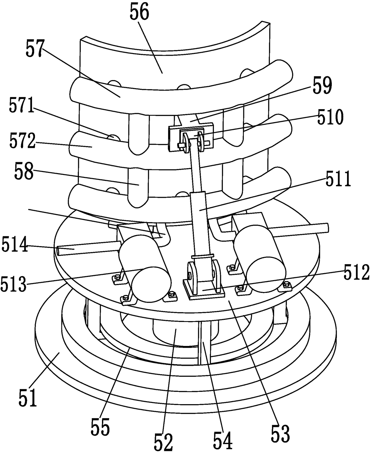
[0022] Such as Figure 1 to Figure 6 As shown, an automatic equipment for dust prevention and treatment of rock drilling and perforation operations in quarries includes a base plate 1, four universal wheels 2 are symmetrically installed on the lower end surface of the base plate 1, and handrails are arranged on the rear side of the upper end surface of the base plate 1. 3. Two crossbars 4 are arranged on the handrail 3. The crossbar 4 plays a role in enhancing the supporting strength of the handrail 3. The staff drives the invention to move to the down-the-hole drilling rig with the help of the four universal wheels 2 through the handrail 3. Rock perforation position; the left side of the upper end surface of the base plate 1 is equipped with a ...


PUM


Abstract

The invention relates to an automatic device for prevention and treatment of dust in a quarry drilling perforation operation. The automatic device comprises a bottom plate, four universal wheels are symmetrically installed on the lower end surface of the bottom plate, an armrest is arranged on the back side of the upper end face of the bottom plate, two crossbars are arranged on the armrest, and astaff moves the automatic device through the armrest with the assistance of four universal wheels to the perforation position of the drilling perforation of a down-the-hole drill; the left side of the upper end surface of the bottom plate is provided with a spraying device, and the spraying device can realize the spraying and dust-removing function during the drilling perforation of the down-the-hole drill; and the right side of the upper end surface of the bottom plate is provided with a dust suction device which can realize the automatic dust-suction function during the drilling perforationof the down-the-hole drill. The automatic device can simultaneously realize the function of spraying and dust removing and the function of automatic dust suction during the drilling perforation of the down-the-hole drill, and has the advantages of no manual adjustment of spray operation, automatic adjustment of spray angle, simple and convenient operation, high degree of automation, good sprayingeffect, vacuuming by means of activities, adjustable dust-suction direction, high dust-suction speed, and good vacuum effect.

Description

[0001] The present invention is a divisional application of a Chinese patent application filed on September 22, 2016 with the application number 201610837797X, and the title of the invention is a spray vacuum robot for down-the-hole drilling rig drilling. technical field [0002] The invention relates to the technical field of quarry mining, in particular to an automatic equipment for dust prevention and treatment in rock drilling and perforation operations in a quarry. Background technique [0003] The domestic non-coal open-pit mining technology is mainly based on rock drilling and perforation. Rock drilling and perforation is mainly completed by down-the-hole drilling rigs. After the ore is broken into loose blocks, the ore is loaded and transported by a loader or excavator. The mining technology and method of the mining face. Because the quarry is located in the wild and the surrounding environment is harsh, coupled with open-air operations, the large amount of dust gene...

Claims


Application Information

Patent Timeline
Patent Type & Authority Applications(China)
IPC IPC(8): E21F5/04E21F5/20E21B21/01
CPCE21B12/00E21B21/01E21F5/04E21F5/20
Inventor 潘春燕
Owner 潘春燕
Learn More