Supercharge Your Innovation With Domain-Expert AI Agents!

Axial force balance device

A technology of balancing device and axial force, applied in the components of pumping device for elastic fluid, non-variable-capacity pump, machine/engine, etc., to achieve the effect of being conducive to individual debugging

Inactive Publication Date: 2018-06-01
AECC SHENYANG ENGINE RES INST
View PDF4 Cites 7 Cited by
  • Summary
  • Abstract
  • Description
  • Claims
  • Application Information

AI Technical Summary

Problems solved by technology

In the existing technical solutions, the axial force rod is located in the center of the axis, which can only be used to balance the axial force of one rotor

Method used


Image

  • Axial force balance device

Examples


Embodiment Construction

[0013] In order to make the objectives, technical solutions and advantages of the present invention clearer, the technical solutions in the embodiments of the present invention will be described in more detail below in conjunction with the drawings in the embodiments of the present invention. In the drawings, the same or similar reference numerals denote the same or similar elements or elements having the same or similar functions throughout. The described embodiments are some, but not all, embodiments of the invention. The embodiments described below by referring to the figures are exemplary and are intended to explain the present invention and should not be construed as limiting the present invention. Based on the embodiments of the present invention, all other embodiments obtained by persons of ordinary skill in the art without creative efforts fall within the protection scope of the present invention.

[0014] The axial force balance device of the present invention will b...


PUM


Abstract

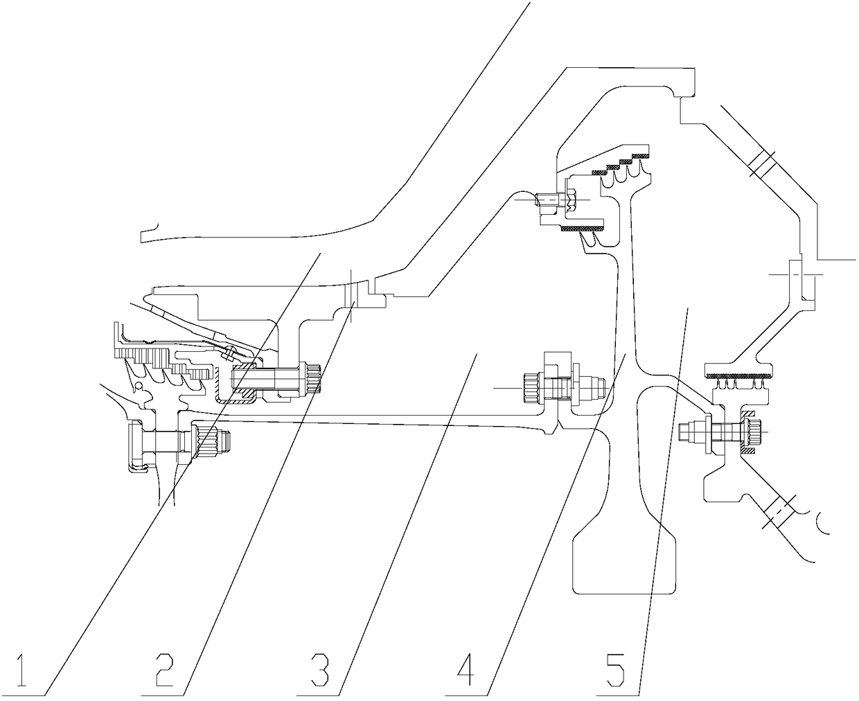
The invention provides an axial force balance device. The device is applied to double-rotor tests; a balance disc (4) is arranged behind a rotor part; a comb tooth row is arranged at the outer diameter of the balance disc (4); the outer side of the comb tooth row is connected with the wall surface of a receiver through a contact connecting module, so that front and back accommodating cavities areformed in the two sides of the balance disc (4); pressure building holes (2) are formed in the peripheral direction of the wall surface of the receiver in the front accommodating cavity of the balancedisc (4) for leading high-pressure gas in an exhaust duct (1) into the front accommodating cavity of the balance disc (4) to form a high-pressure cavity (3); atmosphere is introduced in the back accommodating cavity of the balance disc (4) to form a low-pressure cavity (5); and a front-back pressure difference is acted on the balance disc (4) to counteract axial force. In the axial force balancedevice, through structural design of a balance disc balance device in a gas compressor test piece range, the axial force balance is realized in a gas compressor; and decoupling with external equipmentis realized, so that single equipment debugging is more facilitated.

Description

technical field [0001] The invention belongs to the field of aero-engine design, in particular to the field of compressor testing, and in particular to an axial force balance device. Background technique [0002] When the compressor rotor rotates at high speed, due to the aerodynamic force acting on the blades, it will generate an axial force forward along the axis, and this axial force will finally act on the ball bearing of the rotor. If the axial force is too large, it will cause the bearing to break Abrasion, even damage and failure, in order to ensure the safe operation of the rotor, a tie rod with a threaded head is commonly used to connect with the rotor, and the other end of the tie rod acts on the test bench equipment to offset the axial force. In the prior art solution, the axial force pull rod is located at the center of the axis and can only be used for axial force balance of one rotor. The balance ability depends on the equipment ability, or the balance ability...

Claims


Application Information

Patent Timeline
Patent Type & Authority Applications(China)
IPC IPC(8): F04D29/66
CPCF04D29/662
Inventor 赵雷白志刚李晓冲
Owner AECC SHENYANG ENGINE RES INST
Features
  • R&D
  • Intellectual Property
  • Life Sciences
  • Materials
  • Tech Scout
  • Unparalleled Data Quality
  • Higher Quality Content
  • 60% Fewer Hallucinations
Learn More