Brake band for speed reduction clutch

A technology of deceleration clutch and brake belt, applied in the direction of brake parts, brake types, brake components, etc., can solve the problem that the effective joint surface of the brake belt and the brake hub cannot be fully implemented, the vibration of the brake belt and the brake hub noise, Affect the normal use of the deceleration clutch, etc., to reduce the low life of the steel belt, prevent noise, and not easily deform

Inactive Publication Date: 2018-06-01
余姚市馨洁水暖有限公司
View PDF0 Cites 1 Cited by
  • Summary
  • Abstract
  • Description
  • Claims
  • Application Information

AI Technical Summary

Problems solved by technology

In this kind of brake band structure, the steel band is an integral structure. Due to the repeated tension and release of the brake band during the working process, the steel band will break due to fatigue for a long time, which reduces the life of the brake band. , affecting the normal use of the deceleration clutch; and when the brake band and the brake hub are in contact, due to the influence of the natural resilience of the steel belt after forming, the initial effective joint surface of the brake band and the brake hub cannot be fully implemented. After working for a period of time, the braking force Due to the influence of torque, the brake belt will be deformed, and the washing machine will vibrate greatly during dehydration, which will cause the brake belt and the brake hub to rub against each other and generate noise, which will affect the normal use of the washing machine.

Method used


Image

  • Brake band for speed reduction clutch
  • Brake band for speed reduction clutch

Examples


Embodiment Construction

[0011] The present invention will be further described in detail below in conjunction with the accompanying drawings and embodiments.

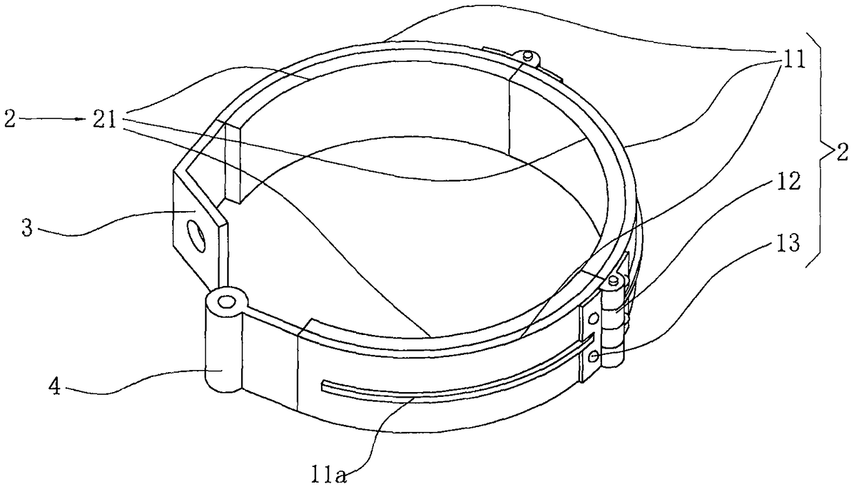
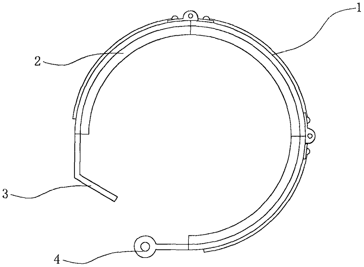
[0012] like Figure 1~2 As shown, the brake band used for the deceleration clutch in this embodiment includes a steel band 1, a friction band 2, a fixed plate 3 and a pin joint 4, the friction band 2 is bonded to the steel band 1, the fixed plate 3 and the pin The shaft joints 4 are respectively connected to the two ends of the steel belt 1. The steel belt 1 includes three sections of steel belt 11, and the three sections of steel belt 11 are connected together by hinges 12 and rivets 13. The friction belt 2 includes three sections corresponding to the sub-steel belts. The sub-friction belt 21, in addition, a reinforcing rib 11 along the horizontal direction is arranged in the middle of the sub-steel belt 11 to increase the strength of the sub-steel belt 11.

[0013] The above is only the preferred embodiment of the present invention, it shou...


PUM


Abstract

The invention relates to a brake band for a speed reduction clutch. The brake band for the speed reduction clutch comprises a steel band, a friction band, a fixing plate and a hinge pin connector. Thefriction band adheres to the steel band, and the fixing plate and the hinge pin connector are connected to the two ends of the steel band correspondingly. The brake band for the speed reduction clutch is characterized in that the steel band comprises at least two son steel band segments which are connected through a hinge and a rivet, the friction band comprises at least two son friction band segments corresponding to the son steel band segments, and the son steel band segments are provided with reinforcing ribs. By means of the steel band which is arranged in a segment manner, it can be guaranteed that in the tensioning and releasing process of the steel band, bending stress repeatedly generated by the steel band is reduced through the hinge for mutual connection, and the situation thatthe service life of the steel band is relatively short or breaking accidents are prone to being caused by fatigue is effectively reduced. By means of the arrangement of the reinforcing ribs, the strength of the steel band is enhanced, the brake band is not prone to being deformed, and noise generated by mutual friction, caused by large dewatering vibration, between the brake band and a brake hub is prevented.

Description

technical field [0001] The invention relates to the technical field of the deceleration clutch of a washing machine, in particular to a braking band used on the deceleration clutch. Background technique [0002] The full-automatic pulsator washing machines sold on the existing market are all provided with deceleration clutches, which are used as transmission parts to reduce the rotating speed of the motor and increase the torque to drive the pulsator to work. The current deceleration clutch generally adopts a brake band for braking. The above-mentioned brake band generally includes a steel band, a friction band, a pin joint and a fixed plate. The friction band is bonded to the steel band, and the pin joint and the fixed plate are respectively connected with both ends. In this kind of brake band structure, the steel band is an integral structure. Due to the repeated tension and release of the brake band during the working process, the steel band will break due to fatigue for...

Claims


Application Information

Patent Timeline
Patent Type & Authority Applications(China)
IPC IPC(8): F16D65/06F16D69/04D06F37/30
CPCF16D65/067D06F37/30F16D69/0416F16D2069/0433F16D2069/0466
Inventor 周栋
Owner 余姚市馨洁水暖有限公司
Why Eureka
Try Eureka