
Locking plate assembling machine for connector

A technology of connectors and assembly machines, which is applied in the direction of connection, assembly/disassembly of contacts, circuit/collector parts, etc., which can solve the problems of inability to realize terminal insertion, consume human resources, and low processing efficiency, etc., and achieve simple structure , to ensure accuracy and improve efficiency

Active Publication Date: 2018-06-01
苏州市相城区黄桥工业园经济发展有限公司
View PDF3 Cites 3 Cited by
  • Summary
  • Abstract
  • Description
  • Claims
  • Application Information

AI Technical Summary

Problems solved by technology

[0002] A connector is a commonly used electronic component, which is mainly composed of a connector body and terminals, such as Figure 21 It is a connector with terminals inserted. In order to make the terminals inserted stably, the main body of the connector will have a lock piece groove, which needs to be locked by inserting the lock piece. Most of the existing lock pieces are inserted into the connector. Fixing, put the locking piece on it, and then press it tightly through the pressing device. The processing efficiency of this method is low, and continuous terminal insertion cannot be achieved. At the same time, the locking piece must be placed manually, which consumes a lot of time. Human Resources

Method used


Image

  • Locking plate assembling machine for connector
  • Locking plate assembling machine for connector
  • Locking plate assembling machine for connector

Examples


Embodiment Construction

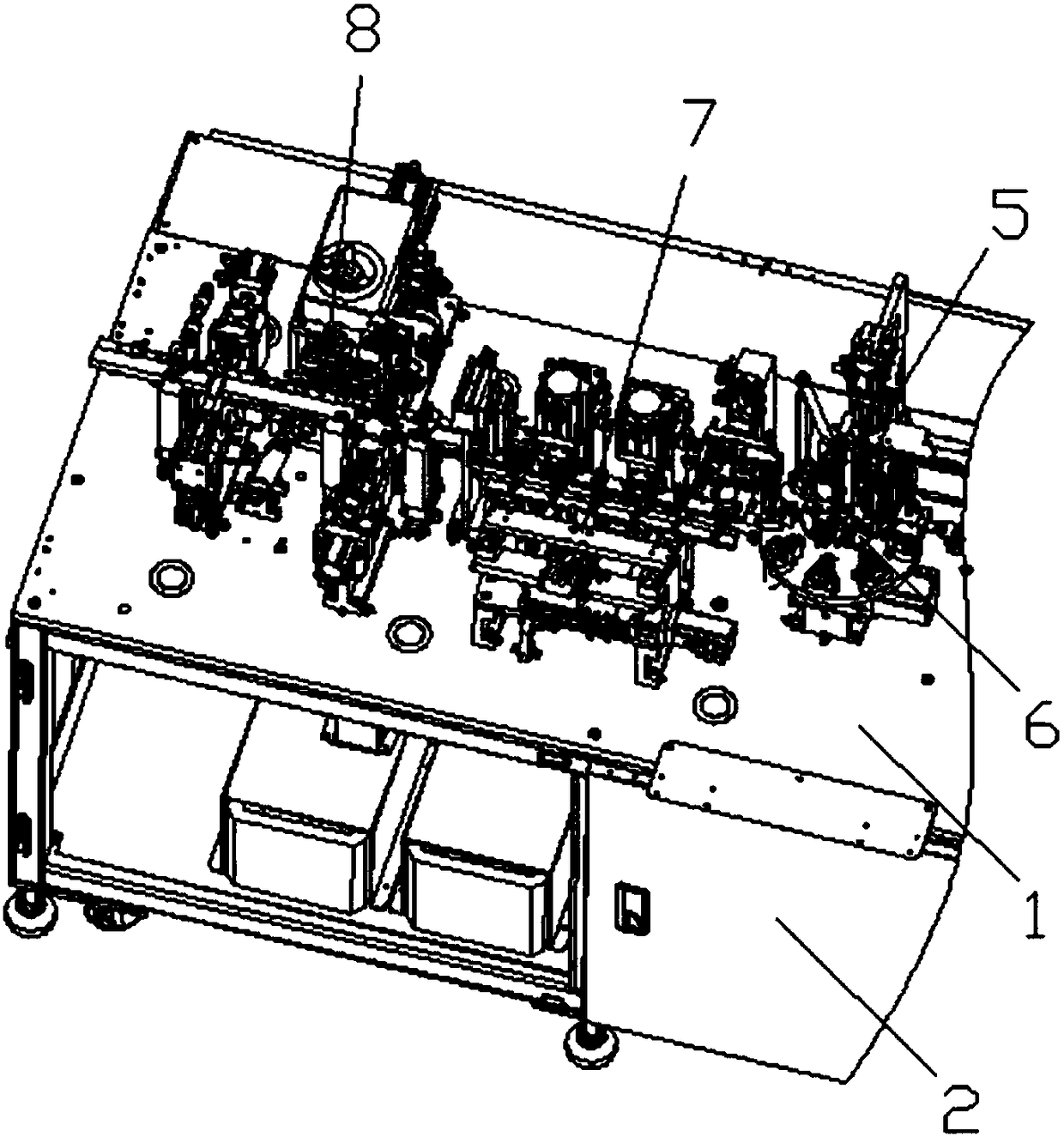
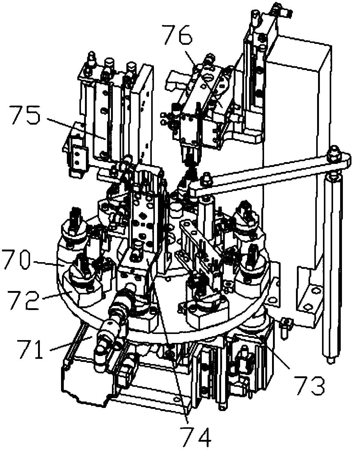
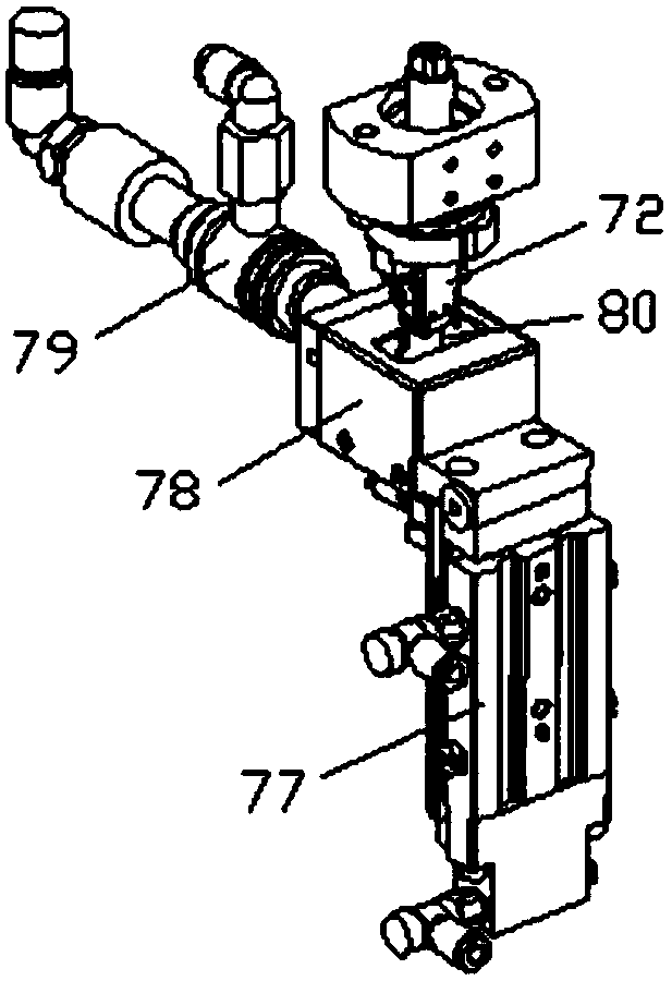
[0044] Such as Figure 1-20As shown, the specific structure of the present invention is: a lock plate assembly machine for connectors, including a frame 1 and a power distribution control box 2, the frame 1 is provided with a lock plate insertion mechanism 8, the described The lock piece insertion mechanism 8 includes a lock piece insertion delivery groove 141 and a lock piece insertion feeding device 142 which are arranged on the frame 1 and cooperate with each other. device 143, the lock plate material overturning device 143 includes a forward and backward clamping material propelling cylinder 158, the clamping material propelling cylinder 158 is connected with a material overturning motor 159, and the material overturning motor 159 is connected with the lock Insert the card material turning block 160 docked with the conveying groove 141. The rear side of the card material turning block 160 is provided with a vertical locking plate conveying device 144, and the upper side of...


PUM


Abstract

The invention relates to a locking plate assembling machine for a connector. The locking plate assembling machine comprises a locking plate inserting mechanism. The locking plate inserting mechanism comprises a locking plate inserting conveying slot and a locking plate inserting feeding device. The middle of the locking plate inserting conveying slot cooperates with a locking plate clamping material overturning device. The rear side of a clamping material overturning block is provided with a vertically extending locking piece conveying device. A locking plate clamping device is arranged abovethe side portion of the locking plate conveying device. A locking plate carrier tape cutting device and a locking plate pressure device are arranged below the side portion of the locking plate conveying device. A locking plate inserting device is disposed behind the locking plate conveying device. The purpose of the invention is to provide a locking piece assembling machine for a connector. A locking plate is made into a carrier tape and is conveyed vertically by the locking plate conveying device. The same cam drive device is configured to drive the locking plate clamping device, the lockingplate carrier tape cutting device, the locking plate pressure device, the locking plate inserting device push the locking plate forward and backward, and can achieve continuous insertion of the locking plate in cooperation with the locking plate inserting conveying slot. The locking plate assembling machine can ensure the accuracy of inserting the locking plate, greatly improves the efficiency ofinserting the locking plate.

Description

technical field [0001] The invention relates to the field of processing equipment for connectors, in particular to a lock plate assembly machine for connectors. Background technique [0002] A connector is a commonly used electronic component, which is mainly composed of a connector body and terminals, such as Figure 21 It is a connector with terminals inserted. In order to make the terminals inserted stably, the main body of the connector will have a lock piece groove, which needs to be locked by inserting the lock piece. Most of the existing lock pieces are inserted into the connector. Fixing, put the locking piece on it, and then press it tightly through the pressing device. The processing efficiency of this method is low, and continuous terminal insertion cannot be achieved. At the same time, the locking piece must be placed manually, which consumes a lot of time. human Resources. Contents of the invention [0003] The purpose of the present invention is to provide a...

Claims


Application Information

Patent Timeline
Patent Type & Authority Applications(China)
IPC IPC(8): H01R43/20
CPCH01R43/048H01R43/055H01R43/20
Inventor 刘晓蔚赖梦瑶程发良
Owner 苏州市相城区黄桥工业园经济发展有限公司
Learn More