Terminal bending equipment

A terminal and equipment technology, applied in the field of terminal production equipment, can solve the problems of low bending and insertion efficiency, unfavorable large-scale production, waste of manpower and material resources, etc., and achieves the effect of simple structure, convenient operation and improved work efficiency.

Inactive Publication Date: 2019-02-22
DONGGUAN RONGGONG AUTOMATION TECH CO LTD
View PDF9 Cites 3 Cited by
  • Summary
  • Abstract
  • Description
  • Claims
  • Application Information

AI Technical Summary

Problems solved by technology

[0007] Most of the terminal blanks obtained after production are rolled. In the existing terminal bending and insertion process, most of the blank rolls need to be divided into single terminal blanks first, and then the terminals are put into the bending device for bending. , and then manually or mechanically insert the bent ordinary terminals into the terminal one by one to obtain the finished product. This method consumes a lot of manpower and material resources, and at the same time the efficiency of bending and insertion is low, which is not conducive to large-scale Production

Method used


Image

  • Terminal bending equipment
  • Terminal bending equipment
  • Terminal bending equipment

Examples


Embodiment Construction

[0037] In order to enable those skilled in the art to better understand the technical solution of the present invention, the present invention will be described in detail below in conjunction with the accompanying drawings. The description in this part is only exemplary and explanatory, and should not have any limiting effect on the protection scope of the present invention. .

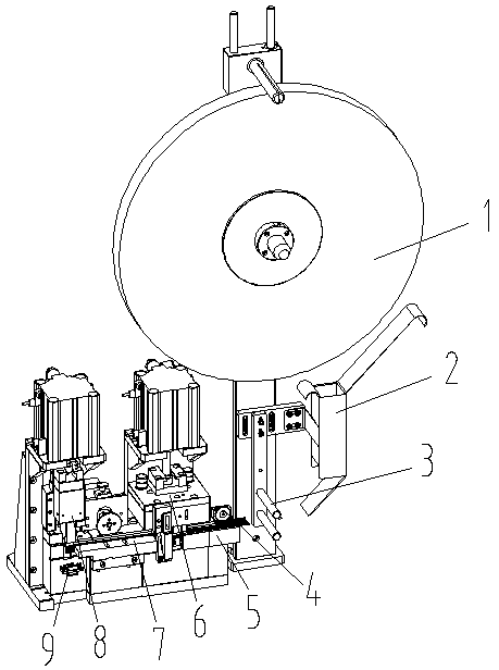
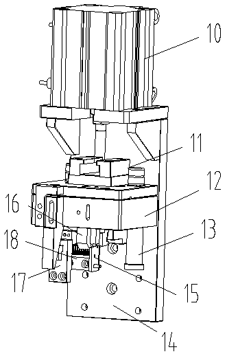
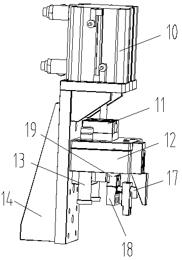
[0038] Such as Figure 1-Figure 8 As shown, the specific structure of the present invention is: a terminal bending equipment, which includes a blank roll 1 arranged on a support, and the blank roll 1 is matched with a conveying block through a guide groove 2 and a guide cylinder 3. The conveying block is provided with a cover plate that cooperates with the blank roll 1. The middle part of the conveying block is provided with a bending mechanism 6, and the tail is provided with an insertion device 8 that cooperates with the terminal insertion seat 901. The bending mechanism Both sides of 6 are provided...


PUM


Abstract

The invention relates to terminal bending equipment. The terminal bending equipment is characterized in that a workblank coil is provided with conveying blocks through a guide groove and a guide cylinder in a cooperative mode, a cover plate cooperating with the workblank coil is arranged on the conveying blocks, a bending mechanism is arranged between the conveying blocks, the tail part of one conveying block is provided with an inserting device cooperating with a terminal inserting seat, the two sides of the bending mechanism are correspondingly provided with pulling devices cooperating withthe workblank coil, the pulling devices comprise pulling motors arranged on supports, pulling wheels are arranged on the pulling motors, and pulling columns which are matched with the holes in a terminal workblank are uniformly arranged on the pulling wheels. According to the terminal bending equipment, the conveying blocks cooperating with the workblank coil are arranged, the bending mechanism isarranged between the conveying blocks, the inserting device cooperating with the terminal inserting seat is arranged at the tail part of one conveying block, and meanwhile, the pulling device cooperating with the terminal workblank on the workblank coil are arranged on the conveying blocks, so that the workblank coil does not need to be segmented, meanwhile, the two passes of procedures of bending and inserting can be completed at one time, and the working efficiency of terminal insertion is greatly improved.

Description

[0001] Original application number: 2016112183905 [0002] Date of original filing: December 26, 2016 [0003] Applicant of the original case: Dongguan Ronggong Automation Technology Co., Ltd. [0004] Original application name: an automatic bending and inserting machine for terminals. technical field [0005] The invention relates to the field of terminal production equipment, in particular to terminal bending equipment. Background technique [0006] In electrical engineering, terminals refer to terminal terminals, also called terminal blocks. Common terminals are mostly holes. When in use, it is necessary to first bend the terminal blank into an angle of 90 degrees, and then insert the terminal into the The terminals are inserted into the sockets to obtain as Figure 8 The finished product composed of the middle terminal insertion seat 901 and the common terminal 902 . [0007] Most of the terminal blanks obtained after production are rolled. In the existing terminal be...

Claims


Application Information

Patent Timeline
Patent Type & Authority Applications(China)
IPC IPC(8): B23P19/00B21D11/10H01R43/16
CPCB21D11/10B23P19/00H01R43/16
Inventor 黄红梅
Owner DONGGUAN RONGGONG AUTOMATION TECH CO LTD
Why Eureka
Try Eureka