Sound debugging method and device based on amplitude-frequency response curve

A technology of amplitude-frequency response curve and debugging method, which is applied in the direction of electrical components, etc., can solve problems such as low debugging efficiency, inability to guarantee sound quality, complicated debugging operation, etc., and achieve the effect of improving debugging efficiency and simplifying audio debugging operation

Inactive Publication Date: 2018-06-01
GUANGZHOU LEAFUN CULTURE SCI & TECH
View PDF10 Cites 20 Cited by
  • Summary
  • Abstract
  • Description
  • Claims
  • Application Information

AI Technical Summary

Problems solved by technology

[0006] In addition, because the debugging of the audio system requires the debugging personnel to have a certain understanding of the audio field, most ordinary users cannot do it by themselves

Method used


Image

  • Sound debugging method and device based on amplitude-frequency response curve
  • Sound debugging method and device based on amplitude-frequency response curve
  • Sound debugging method and device based on amplitude-frequency response curve

Examples


Embodiment 1

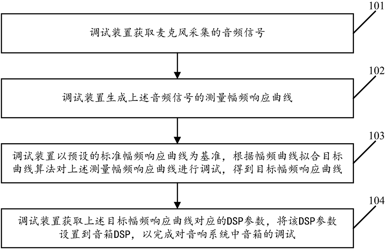
[0069] see figure 1 , figure 1 It is a schematic flowchart of an audio tuning method based on an amplitude-frequency response curve disclosed in an embodiment of the present invention. Such as figure 1 As shown, the audio tuning method based on the amplitude-frequency response curve may include the following operations:

[0070] 101. The debugging device acquires an audio signal collected by a microphone.

[0071] In the embodiment of the present invention, the debugging device can obtain the audio signal collected by the sound input device. In particular, the debugging device can obtain the audio signal collected by the audio signal acquisition sensor of the non-directional measurement microphone, wherein the number of non-directional measurement microphones There may be one or more. Correspondingly, there may be one or more measurement points where the omnidirectional measurement microphone is located, which is not limited in the present invention.

[0072] As an optiona...

Embodiment 2

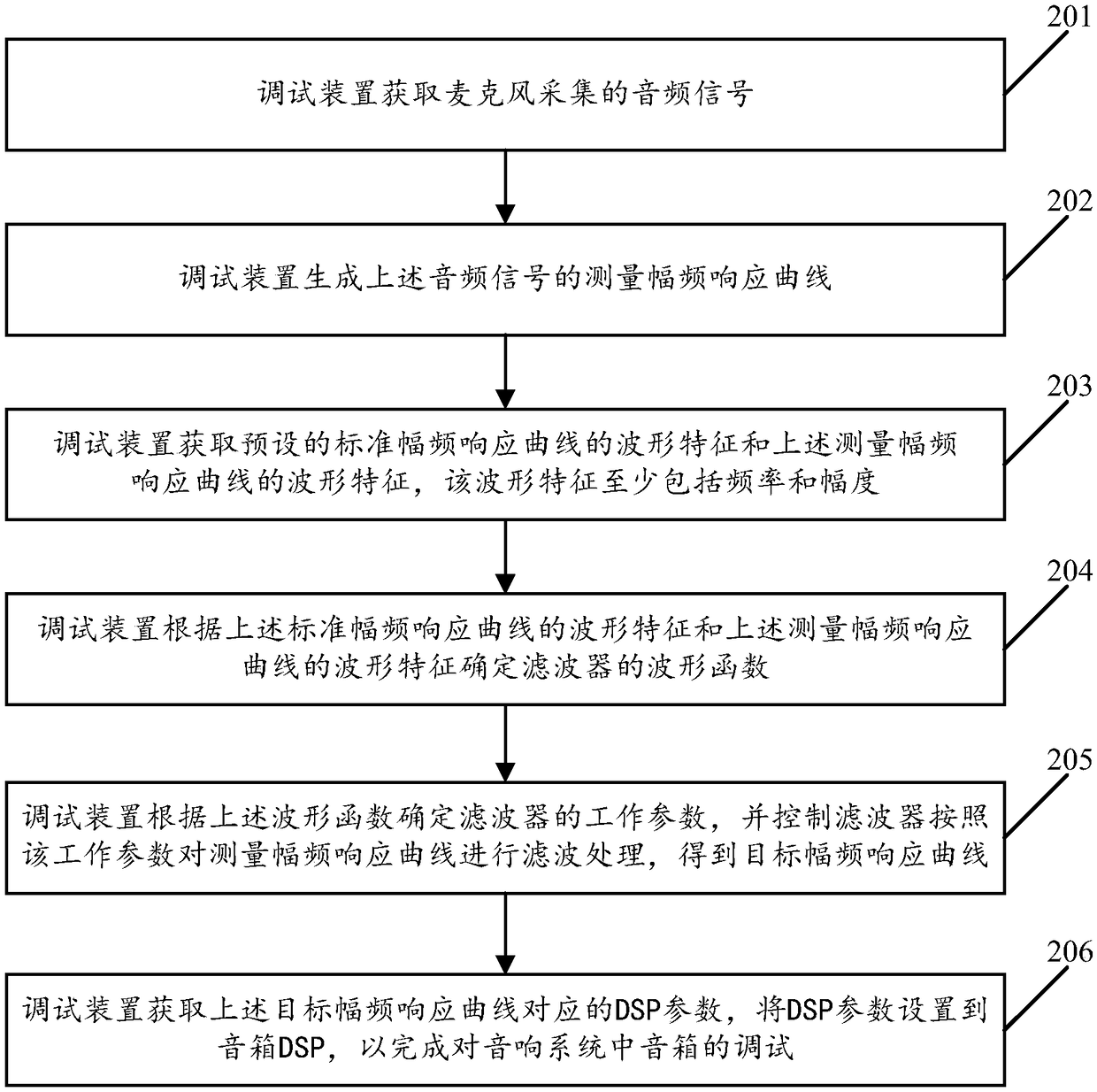
[0095] see figure 2 , figure 2 It is a flow chart of another audio tuning method based on the amplitude-frequency response curve disclosed by the embodiment of the present invention. Such as figure 2 As shown, the audio tuning method based on the amplitude-frequency response curve may include the following steps:

[0096] In the embodiment of the present invention, the audio tuning method based on the amplitude-frequency response curve also includes steps 201-202. For the description of steps 201-202, please refer to the detailed description of steps 201-202 in the first embodiment. The embodiment of the present invention No longer.

[0097] 203. The debugging device acquires the waveform characteristics of the preset standard amplitude-frequency response curve and the waveform characteristics of the above-mentioned measured amplitude-frequency response curve, where the waveform characteristics include at least frequency and amplitude.

[0098] In the embodiment of the ...

Embodiment 3

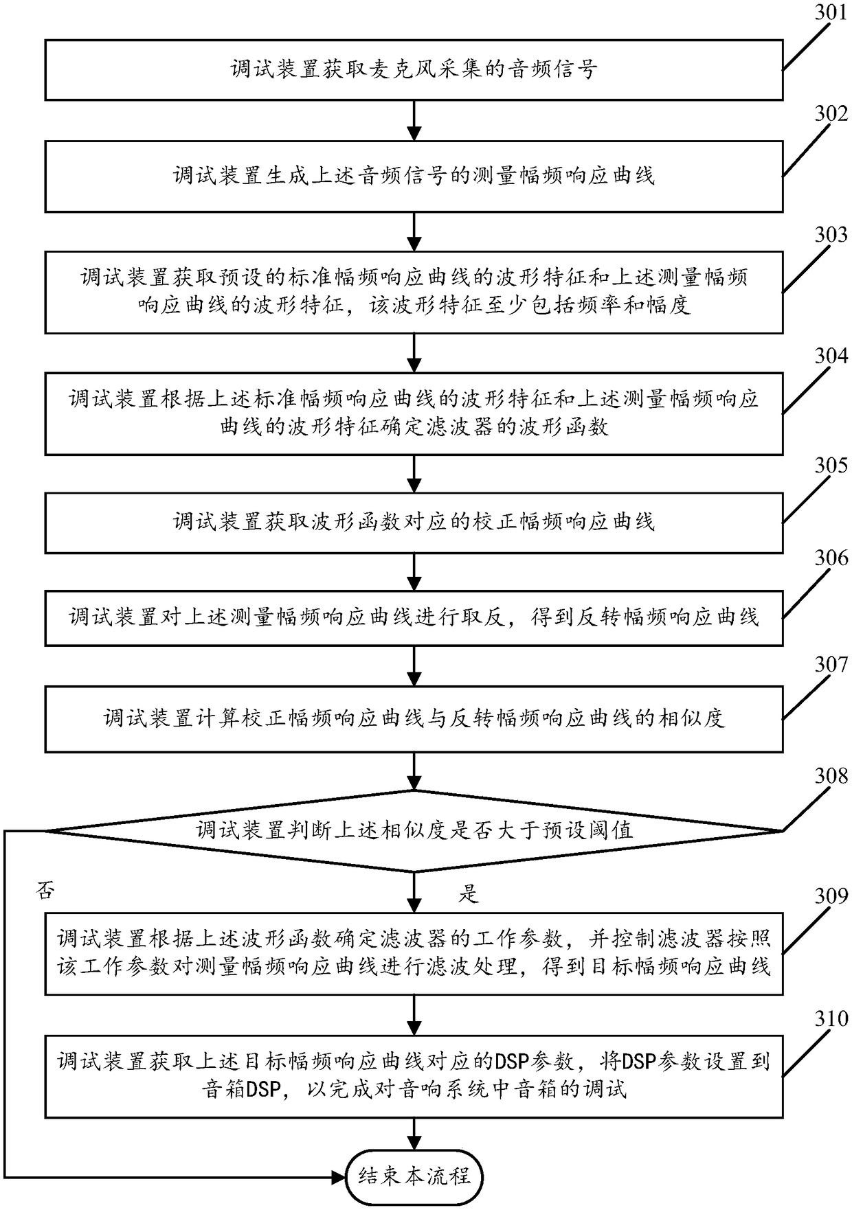
[0117] see image 3 , image 3 It is a flow chart of another audio tuning method based on the amplitude-frequency response curve disclosed in the embodiment of the present invention. Such as image 3 As shown, the audio tuning method based on the amplitude-frequency response curve may include the following steps:

[0118] In the embodiment of the present invention, the audio tuning method based on the amplitude-frequency response curve further includes steps 301-304. For the description of steps 301-304, please refer to the detailed description of steps 201-204 in Embodiment 2. The implementation of the present invention Examples will not be repeated.

[0119] 305. The debugging device acquires a corrected amplitude-frequency response curve corresponding to the waveform function.

[0120] 306. The debugging device inverts the measured amplitude-frequency response curve to obtain an inverted amplitude-frequency response curve.

[0121] In the embodiment of the present inve...


PUM


Abstract

The invention relates to the technical field of sound boxes, in particular to a sound debugging method and device based on an amplitude-frequency response curve; the method comprises the following steps: acquiring an audio signal acquired by a microphone, generating a measurement amplitude-frequency response curve of the audio signal, and then, taking a preset standard amplitude-frequency responsecurve as a reference, debugging the measurement amplitude-frequency response curve according to an amplitude-frequency curve fitting target curve algorithm, obtaining a target amplitude-frequency response curve, obtaining corresponding DSP parameters of the target amplitude-frequency response curve, setting the DSP parameters to a sound box DSP, so as to complete debugging of the sound box in a sound system. Therefore, according to the embodiments of the invention, the sound debugging operation can be simplified, and the debugging efficiency is improved.

Description

technical field [0001] The invention relates to the technical field of audio speakers, in particular to an audio debugging method and device based on an amplitude-frequency response curve. Background technique [0002] The sound field is the space in which sound waves propagate. In the indoor environment, when the user needs to play music through the speaker, the audio signal emitted by the speaker is affected by the sound field during the transmission process, which may easily cause distortion of the audio signal. Therefore, in order to reduce the impact of the sound field on the audio signal, it is necessary The audio signal is processed so that the user can obtain a good listening experience at the listening position. [0003] At present, the conventional debugging method for a sound system composed of speakers is to delay, limit, and Frequency division and other operations to adjust the DSP parameters of the speaker, so that the entire audio system can achieve the best...

Claims


Application Information

Patent Timeline
IPC IPC(8): H04R29/00
CPCH04R29/00
Inventor 李志雄黄石峰李株亮张国标
Owner GUANGZHOU LEAFUN CULTURE SCI & TECH
Why Eureka
Try Eureka