Machining method of turbine blade

A turbine blade cutting technology, applied in metal processing equipment, metal processing machinery parts, manufacturing tools, etc., can solve the problems of high design cost, hindering chip falling, and adverse effects of turbine blade accessibility, etc., to achieve processing accuracy simple effect design

Active Publication Date: 2020-11-17
GF MACHINING SOLUTIONS AG
View PDF3 Cites 0 Cited by
  • Summary
  • Abstract
  • Description
  • Claims
  • Application Information

AI Technical Summary

Problems solved by technology

This back brace requires a relatively large amount of space around the turbine blades, requires additional drives, adversely affects the accessibility of the turbine blades, and may hinder the falling of chips
Furthermore, during the change of the contour section to be machined, the backing must be bypassed by the tool, which requires considerable design effort and in any case entails a certain risk of collisions
In addition, the finished vane surface can be damaged by the plunger, for example, imprinted by the plunger

Method used


Image

  • Machining method of turbine blade
  • Machining method of turbine blade

Examples


Embodiment Construction

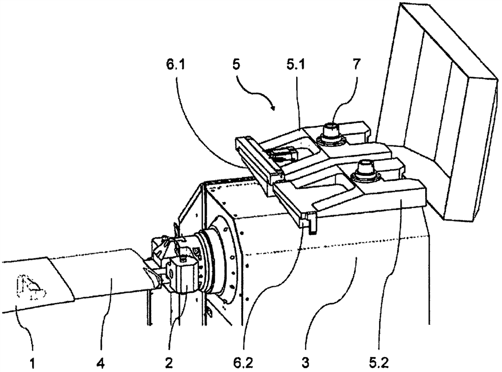
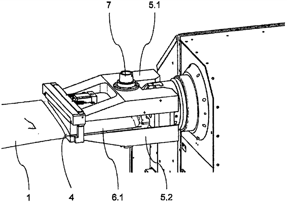
[0012] These two figures show in a perspective view the area of ​​a machine tool during the machining of a turbine blade 1 with a rotatably driven blade tip clamping device 2 therein. The shaft and drive of the blade tip clamping device 2 are housed in the housing 3 . A blade root clamping device is provided, which is arranged opposite to the blade tip clamping device 2, and a tool shaft is provided which is at an angle to the longitudinal axis of the turbine blade 1, but not shown in the figure. figure 1 As shown in , the first profile section 4 adjacent to the blade tip has been machined by the tool. This machining is not necessarily finishing machining. It is only important that the profile section provides a defined, stable contact surface for the gripper jaws mentioned below.

[0013] An additional clamping device 5 consisting of two parts 5.1 and 5.2 for stabilizing the first profile section 4 is mounted on the housing 3, which is used in accordance with figure 1 Appl...


PUM


Abstract

The invention provides a method for cutting a turbine blade. In the method for cutting a turbine blade (1) on a multi-axis machine tool, the turbine blade (1) is held by a rotatable blade root clamping device and a rotatable blade tip clamping device (2), and the The tool clamped in the tool spindle is machined. First the first contour section ( 4 ) adjacent to the blade tip is machined by the tool, and then the tool is removed. The tool spindle then grips the already horizontal additional clamping device (5), which has jaws (6.1, 6.2) adapted to the first contour section (4). The additional clamping device (5) is positioned on the blade tip clamping device (2) in such a way that the clamping jaws (6.1, 6.2) are seated in the first contour section (4). The tool spindle then grips the tool and uses it to machine the remaining contour section.

Description

technical field [0001] The invention relates to a method for machining a turbine blade on a multi-spindle machine tool, wherein the turbine blade is held by a rotatable blade root clamping device and a rotatable blade tip clamping device and is utilized in a tool spindle The clamped tool is processed. Background technique [0002] Elastic bending of turbine blades caused by cutting forces is a known problem in this approach. This curvature has a negative effect on the accuracy of the machining and can lead to vibrations of the turbine blade, thereby resulting in an impairment of the surface quality of the machined contour section. [0003] A solution to the above-mentioned problem is known from document EP2618961B1, in which a turbine blade is supported in certain sections during machining by means of a back brace that can travel along the blade axis. The back brace has plungers movable along their own axis and pressed against the turbine blade in order to support it. Thi...

Claims


Application Information

Patent Timeline
Patent Type & Authority Patents(China)
IPC IPC(8): B23D79/00
CPCB23D79/00B23C3/18B23Q2230/002B23Q2230/006B23Q3/063B23P15/02B23Q3/06B23Q2240/007B23Q2703/10
Inventor M·斯塔雷克
Owner GF MACHINING SOLUTIONS AG
Why Eureka
Try Eureka