Viaduct type portal machine tool high in rigidity, strength and stability
A processing machine tool and stability technology, applied in the direction of metal processing machinery parts, metal processing equipment, manufacturing tools, etc., can solve the problems of difficult to guarantee accuracy, difficult to adjust, difficult to install, etc., to achieve high-speed processing, simple structure, avoid The effect of beam twist
- Summary
- Abstract
- Description
- Claims
- Application Information
AI Technical Summary
Problems solved by technology
Method used
Image

Examples
Embodiment Construction
[0032] The present invention will be described in detail below in conjunction with specific embodiments and accompanying drawings.
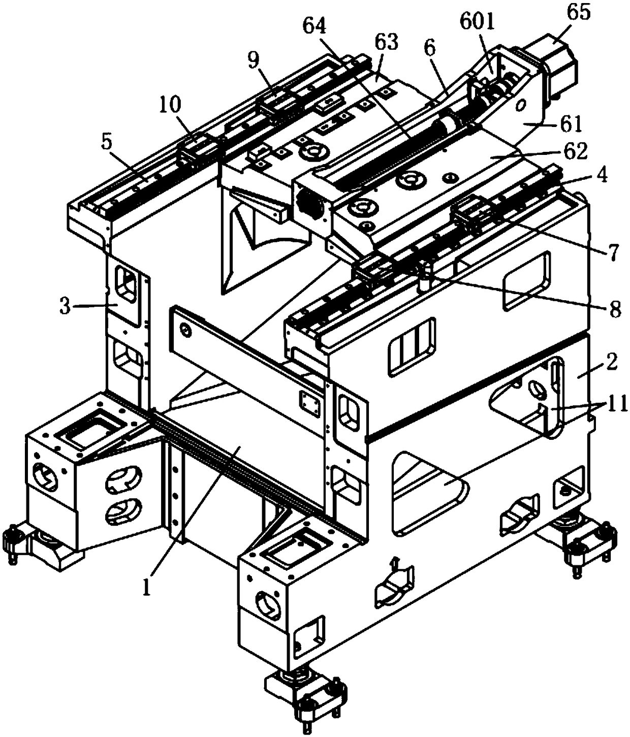
[0033] A kind of viaduct type gantry processing machine tool with good rigidity and stability of this embodiment, such as figure 1 As shown, it includes a base 1, a first bridge seat 2 and a second bridge seat 3 respectively arranged on both sides of the base 1, a first line rail 4 arranged on the first bridge seat 2, and a first line rail 4 arranged on the second bridge seat 3 The second line rail 5 on the top, the Y-axis feed system 6 that is slidingly connected with the first line rail 4 and the second line rail 5 at both ends; wherein, the Y-axis feed system 6 includes a screw seat 61, which is respectively connected to the screw rod The first shoulder seat 62 and the second shoulder seat 63 on both sides of the seat 61, the screw mandrel 64 that is arranged on the screw mandrel seat 61, the motor 65 that is arranged on the rear end of the sc...
PUM
 Abstract
Description
Claims
Application Information
 - Generate Ideas
- Intellectual Property
- Life Sciences
- Materials
- Tech Scout
- Unparalleled Data Quality
- Higher Quality Content
- 60% Fewer Hallucinations
Browse by: Latest US Patents, China's latest patents, Technical Efficacy Thesaurus, Application Domain, Technology Topic, Popular Technical Reports.
© 2025 PatSnap. All rights reserved.Legal|Privacy policy|Modern Slavery Act Transparency Statement|Sitemap|About US| Contact US: help@patsnap.com