
A pipe transportation device

A technology for transporting equipment and pipes, applied in the field of transportation, can solve the problems of not keeping the axis of the tubular product perpendicular to the transportation direction, and not being able to transport tubular products of different sizes.

Active Publication Date: 2020-04-21
宁波隆锐机械制造有限公司
View PDF5 Cites 0 Cited by
  • Summary
  • Abstract
  • Description
  • Claims
  • Application Information

AI Technical Summary

Problems solved by technology

[0004] The present invention intends to provide a pipe transportation equipment to overcome the problems in the prior art that the pipe products of different sizes cannot be transported and the axis of the pipe products cannot be kept perpendicular to the transportation direction

Method used


Image

  • A pipe transportation device
  • A pipe transportation device
  • A pipe transportation device

Examples


Embodiment Construction

[0017] The present invention will be described in further detail below by means of specific embodiments:

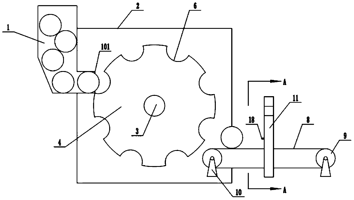
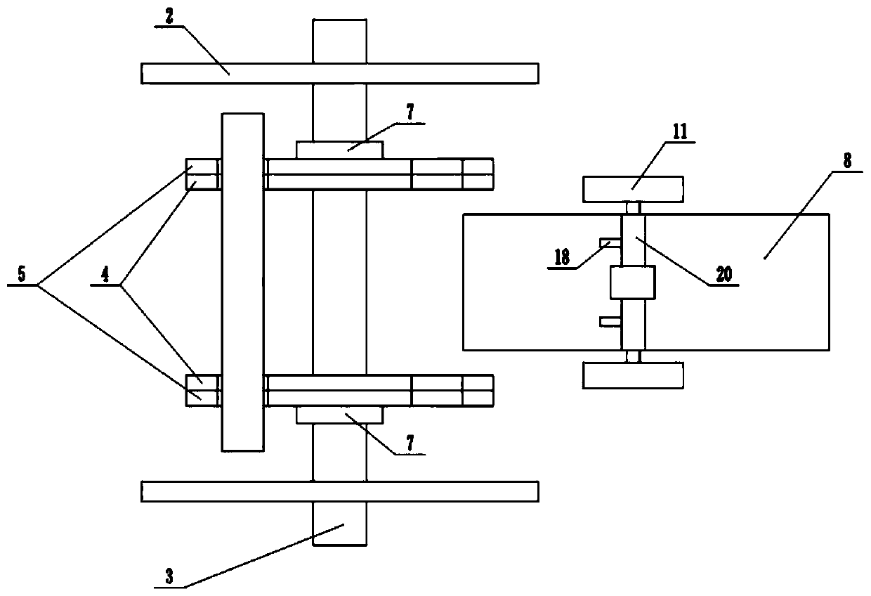
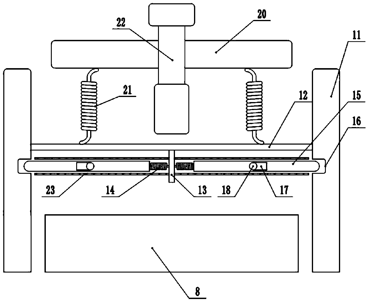
[0018] The reference signs in the drawings of the description include: unloading device 1, discharge port 101, housing 2, rotating shaft 3, feeding tray 4, adjusting disc 5, groove 6, fixing nut 7, conveyor belt 8, runner 9. Rack 10, support plate 11, lower baffle 12, partition 13, elastic member 14, control rod 15, card slot 16, wedge-shaped chute 17, pressing piece 18, wedge-shaped end 19, upper baffle 20, Elastic stretching member 21, air pressure telescopic device 22, limit tube 23.

[0019] The embodiment is basically as attached figure 1 ~ attached Figure 4 Shown: including a blanking device 1, the blanking device 1 is provided with a discharge port 101, the end of the discharge port 101 is connected with a feeding device, one side of the feeding device is provided with a conveying device, and the conveying device The upper end is provided with an adjustment dev...


PUM


Abstract

The invention relates to the technical field of conveying, and discloses a pipe fitting conveying device which comprises a feeding device. A conveying device body is arranged on one side of the feeding device. An adjusting device is arranged at the upper end of the conveying device body. The adjusting device comprises supporting plates distributed on the two sides of the conveying device body. A lower baffle is arranged between the supporting plates. A partition plate is arranged on the lower baffle. The two sides of the partition plate are each connected with an elastic piece. The elastic pieces are each connected with a control rod. A clamping groove is formed in each supporting plate. The control rods are downward inserted in the clamping grooves under the elastic force of the elastic pieces. The control rods are provided with wedge-shaped slide grooves. The control rods are sleeved with limiting pipes which are each provided with a through hole and a pressing piece. The end of eachpressing piece is matched with a wedge-shaped slide groove. An upper baffle is arranged on the upper side of the lower baffle and connected with the lower baffle through an elastic tensile piece. A pneumatic telescopic device is arranged on the upper baffle. Pipe fittings are conveyed through the feeding device, and the conveying direction of the pipe fittings is corrected through the effect of the adjusting device. The pipe fitting conveying device has the advantages that various pipe fittings can be conveyed, and the conveying direction of the pipe fittings can be corrected.

Description

technical field [0001] The invention relates to the technical field of transportation, in particular to a transportation device. Background technique [0002] During the production of pipes in the factory, many different types and specifications of tubular products will be manufactured according to people's various needs. Many tubular products need further processing after the initial molding. Therefore, it is usually necessary to use a dedicated transport pipe. Transport aircraft. [0003] However, in the prior art, a conveyor can only transport a tubular product with a fixed specification, and cannot adapt to the transportation of tubular products of different sizes, and the special equipment has high cost and complex structure; During the process, the axis of the tubular product cannot be transported perpendicular to the conveying direction as required, which will result in the inability of the tubular product to be accurately transported to the next processing equipment...

Claims


Application Information

Patent Timeline
Patent Type & Authority Patents(China)
IPC IPC(8): B65G47/82B65G47/24B65G65/48
CPCB65G47/24B65G47/82B65G65/4881B65G2201/0276
Inventor 项文增
Owner 宁波隆锐机械制造有限公司
Learn More