A high temperature heat transfer oil thermal energy conversion system
What is AI technical title?
AI technical title is built by Patsnap AI team. It summarizes the technical point description of the patent document.
A technology of thermal energy conversion and heat transfer oil, which is applied in heat storage heaters, heat exchange equipment, indirect heat exchangers, etc., can solve the problem of high temperature heat transfer oil cooling, and achieve the effect of precise temperature control and high heat conversion rate
Active Publication Date: 2018-12-21
珠海国能复合材料科技有限公司
View PDF2 Cites 0 Cited by
Summary
Abstract
Description
Claims
Application Information
AI Technical Summary
This helps you quickly interpret patents by identifying the three key elements:
Problems solved by technology
Method used
Benefits of technology
Problems solved by technology
[0005] Aiming at the deficiencies of the prior art, the present invention provides a heat transfer system for high-temperature heat-conducting oil, which solves the technical difficulty of cooling the high-temperature heat-conducting oil at 400°C through the technology of cooling the low-temperature oil with cold water, and then cooling the high-temperature oil with the low-temperature oil. The flow rate of high temperature oil and low temperature oil is controlled by the proportional valve, and the temperature accuracy at high temperature can reach ±1°C
Method used
Image
Click on the blue label to locate the original text in one second.
Reading with bidirectional positioning of images and text.
Examples
Embodiment 1
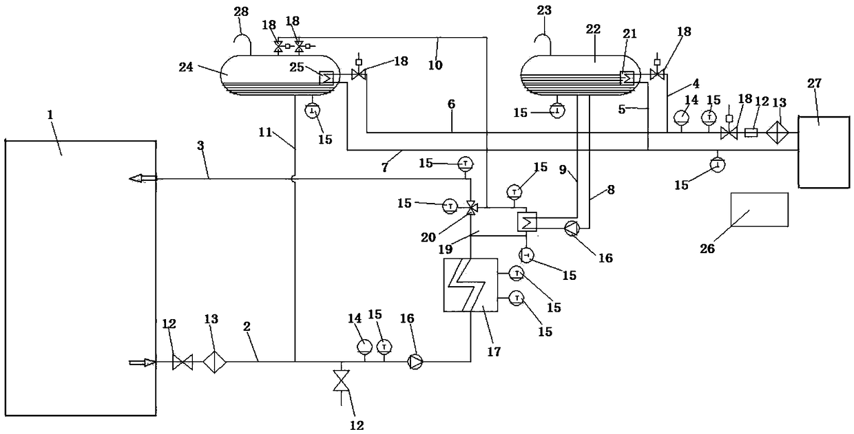
[0031] Embodiment 1, the heat transfer oil outlet of the external device 1 is connected to the heat transfer oil inlet of the heating system 17 through the heat transfer oil return line 2, and the heat transfer oil return line 2 flows from the heat transfer oil outlet of the external device 1 to the direction of the heating system 17. Solenoid valves 12, Filter 13, pressure sensor 14, temperature sensor 15, high temperature heat transfer oil pump 16, solenoid valve 12 and filter 13 are arranged at the intersection point of heat transfer oil return line 2 and expansion heat transfer oil return line 11, close to the heat transfer oil outlet of external device 1 side, the pressure sensor 14, the temperature sensor 15 and the high temperature heat transfer oil pump 16 are arranged at the intersection point of the heat transfer oil return line 2 and the expansion heat transfer oil return line 11 near the side of the heating system 17, and the heat transfer oil in the external equipme...
Embodiment 2
[0032] Embodiment 2, a second heat exchanger 21 is set in the oil storage tank 22, the cooling water inlet of the second heat exchanger 21 is connected to the outlet of the cooling water tower 27 through the cooling water output pipeline 4, and the cooling water outlet is connected to the cooling water outlet through the cooling water return pipeline 5. At the entrance of the water tower 27, a temperature sensor 15 is installed on the oil storage tank 22. The top of the oil storage tank 22 is connected with a first overflow pipe 23. The temperature of the cooling water in the cooling water tower 27 is kept at 15°C. A filter 13, a solenoid valve 12, a flow sensor 18, a temperature sensor 15 and a pressure sensor 14 are sequentially arranged in the direction of the oil storage tank 22; a third heat exchanger 25 is arranged in the expansion oil tank 24, and the third heat exchanger 25 cools the water inlet The cooling water output pipeline 4 is connected to the cooling water outpu...
PUM
Abstract
The invention provides a high temperature heat transfer oil thermal energy conversion system comprising a heat transfer oil return line, a heat transfer oil output line, a cooling water output line, acooling water return line, a cooling water output pipe branch, a cooling water return pipe branch, a cold heat transfer oil output line, a cold heat transfer oil return line, an expanded heat transfer oil output line, an expanded heat transfer oil return line, a heating system, a heat exchanger, a three-way proportional valve, an oil storage tank, an expansion oil tank, a central controller, a cooling water tower, a solenoid valve, a filter, a pressure sensor, a temperature sensor, a flow sensor and an overflow pipe. The heat exchanger includes a first heat exchanger, a second heat exchangerand a third heat exchanger. According to the high temperature heat transfer oil thermal energy conversion system, through a technology of cooling low temperature oil by cold water and then cooling high temperature oil by the low temperature oil, the technical problem of how to cool 400 DEG C low temperature heat transfer oil is solved, the flow of the high temperature oil and the low temperature oil is controlled through the three-way proportional valve, and the temperature precision at the high temperature reaches + / -1 DEG C.
Description
technical field [0001] The invention relates to the field of thermal energy conversion, in particular to a high-temperature heat transfer oil thermal energy conversion system. Background technique [0002] At present, there are not many researches on the 400°C high-temperature heat transfer oil heat exchange system in China. The main reason is that the temperature condition of 400°C is relatively special, and there are hidden dangers of high temperature, high pressure and flammability, and the control is complicated. The temperature accuracy and time cannot be effectively controlled during the cooling stage. At present, the form commonly used for cooling high-temperature heat sources is to cool down through compressed air at a temperature between 400 and 300°C, and to cool down through compressed air at a temperature between 300 and 100°C. Water is used for cooling; such a form of cooling takes a long time, the efficiency is very low, and the temperature cannot be controlled...
Claims
Application Information
Patent Timeline
Application Date:The date an application was filed.
Publication Date:The date a patent or application was officially published.
First Publication Date:The earliest publication date of a patent with the same application number.
Issue Date:Publication date of the patent grant document.
PCT Entry Date:The Entry date of PCT National Phase.
Estimated Expiry Date:The statutory expiry date of a patent right according to the Patent Law, and it is the longest term of protection that the patent right can achieve without the termination of the patent right due to other reasons(Term extension factor has been taken into account ).
Invalid Date:Actual expiry date is based on effective date or publication date of legal transaction data of invalid patent.

