System and method for adjusting position of image sensor

An image sensor and adjustment system technology, applied in the direction of using feedback control, etc., can solve problems such as tendency deviation, operator visual fatigue, adverse effects of enterprises, etc., and achieve the effect of high accuracy and high efficiency

Active Publication Date: 2018-06-05
SHANGHAI SUOGUANG VISUAL PRODUCTS CO LTD
View PDF32 Cites 6 Cited by
  • Summary
  • Abstract
  • Description
  • Claims
  • Application Information

AI Technical Summary

Problems solved by technology

However, due to the relatively heavy proportion of subjective factors in manual visual judgment, there will still be a certain tendency deviation within the specification
At the same time, the high-intensity judgment work of the production line is easy to make the operator's visual fatigue, resulting in misjudgment and misjudgment from time to time
Once defective products enter the market, it will bring many adverse effects to the enterprise

Method used


Image

  • System and method for adjusting position of image sensor
  • System and method for adjusting position of image sensor

Examples


Embodiment 1

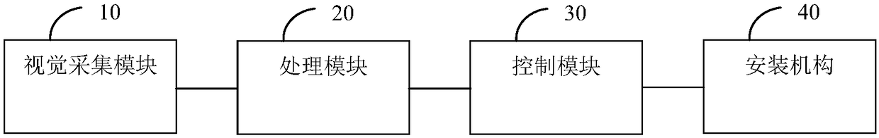
[0040] Such as figure 1 As shown, in a preferred embodiment, a position adjustment system of an image sensor is proposed, which may include:

[0041] A vision acquisition module 10, configured to acquire a visual image of at least one image sensor located on a fixed sheet metal;

[0042] The processing module 20 is connected with the visual acquisition module 10 to receive the visual image, and extract the actual position information of the image sensor from the visual image, and the processing module pre-stores the corresponding standard position information of the image sensor on the fixed sheet metal;

[0043] The processing module 20 compares the actual location information with the standard location information to generate a comparison information and output it;

[0044] The control module 30 is connected with the processing module 20 to receive and generate a control instruction according to the comparison information;

[0045] The installation mechanism 40 is connecte...

Embodiment 2

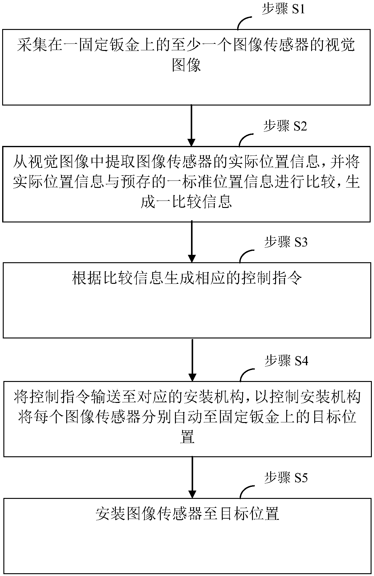
[0067] Such as figure 2 As shown, in a preferred embodiment, a method for adjusting the position of the image sensor is also proposed, which may include:

[0068] Step S1, collecting a visual image of at least one image sensor on a fixed sheet metal;

[0069] Step S2, extracting the actual position information of the image sensor from the visual image, and comparing the actual position information with a pre-stored standard position information to generate comparison information;

[0070] Step S3, generating corresponding control instructions according to the comparison information;

[0071] Step S4, sending the control command to the corresponding installation mechanism, so as to control the installation mechanism to automatically move each image sensor to the target position on the fixed sheet metal;

[0072] Step S5, installing the image sensor to the target position.

[0073] In the above technical solution, the collected visual image may contain the relative position ...


PUM


Abstract

The invention relates to the field of automatic control, and particularly relates to a system and method for adjusting the position of an image sensor. The system comprises a visual acquisition module, a processing module, a control module and an installation mechanism, wherein the visual acquisition module is used for acquiring a visual image of at least one image sensor located on a fixed metalplate; the processing module is connected with the visual acquisition module so as to receive the visual image and extracts actual location information of each image sensor from the visual image, andthe processing module pre-stores standard location information of the corresponding image sensors on the fixed metal plate; the processing module compares the actual location information with the standard location information so as to generate a piece of comparison information and output the comparison information; the control module is connected with the processing module so as to receive the comparison information and generate a control instruction according to the comparison information; and the installation mechanism is connected with the control module so as to receive the control instruction and respectively install each image sensor to the target position on the fixed metal plate according to the control instruction. According to the invention, high-precision automatic positioning can be performed on the installed image sensors, the accuracy is high, and the efficiency is high.

Description

technical field [0001] The invention relates to the field of automatic control, in particular to a system and method for adjusting the position of an image sensor. Background technique [0002] Currently, in the installation process of the image sensor of video equipment, especially the installation adjustment process of the charge-coupled device type image sensor, the conventional method of using manual visual inspection and adjustment is generally used. However, due to the relatively heavy proportion of subjective factors in manual visual judgment, there will still be a certain tendency deviation within the specification. At the same time, the high-intensity judgment work of the production line is easy to make the operator's visual fatigue, resulting in misjudgment and misjudgment from time to time. Once defective products enter the market, it will bring many adverse effects to the enterprise. Contents of the invention [0003] In view of the above problems, the presen...

Claims


Application Information

Patent Timeline
Patent Type & Authority Applications(China)
IPC IPC(8): G05D3/12
CPCG05D3/12
Inventor 马颖隽朱亚敏王智玮
Owner SHANGHAI SUOGUANG VISUAL PRODUCTS CO LTD
Why Eureka
Try Eureka