A system and method for adjusting the position of an image sensor
What is AI technical title?
AI technical title is built by Patsnap AI team. It summarizes the technical point description of the patent document.
An image sensor and adjustment system technology, applied in the direction of control using feedback, etc., can solve the problems of heavy subjective factors, operator visual fatigue, tendency deviation and so on
Active Publication Date: 2021-04-23
SHANGHAI SUOGUANG VISUAL PRODUCTS CO LTD
View PDF32 Cites 0 Cited by
Summary
Abstract
Description
Claims
Application Information
AI Technical Summary
This helps you quickly interpret patents by identifying the three key elements:
Problems solved by technology
Method used
Benefits of technology
Problems solved by technology
However, due to the relatively heavy proportion of subjective factors in manual visual judgment, there will still be a certain tendency deviation within the specification
At the same time, the high-intensity judgment work of the production line is easy to make the operator's visual fatigue, resulting in misjudgment and misjudgment from time to time
Once defective products enter the market, it will bring many adverse effects to the enterprise
Method used
Image
Click on the blue label to locate the original text in one second.
Reading with bidirectional positioning of images and text.
Examples
Embodiment 1
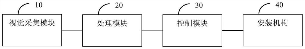
[0040] Such as figure 1 As shown, in a preferred embodiment, a position adjustment system of an image sensor is proposed, which may include:
[0041] A vision acquisition module 10, configured to acquire a visual image of at least one image sensor located on a fixed sheet metal;
[0042] The processing module 20 is connected with the visual acquisition module 10 to receive the visual image, and extract the actual position information of the image sensor from the visual image, and the processing module pre-stores the corresponding standard position information of the image sensor on the fixed sheet metal;
[0043] The processing module 20 compares the actual location information with the standard location information to generate a comparison information and output it;
[0044] The control module 30 is connected with the processing module 20 to receive and generate a control instruction according to the comparison information;
[0045] The installation mechanism 40 is connecte...
Embodiment 2
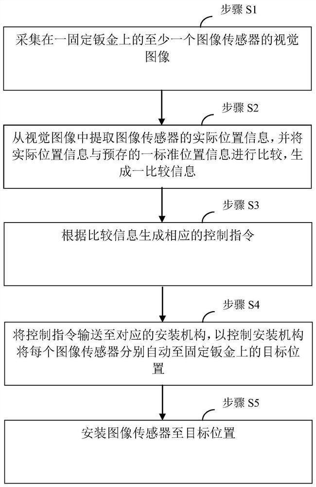
[0067] Such as figure 2 As shown, in a preferred embodiment, a method for adjusting the position of the image sensor is also proposed, which may include:
[0068] Step S1, collecting a visual image of at least one image sensor on a fixed sheet metal;
[0069] Step S2, extracting the actual position information of the image sensor from the visual image, and comparing the actual position information with a pre-stored standard position information to generate comparison information;
[0070] Step S3, generating corresponding control instructions according to the comparison information;
[0071] Step S4, sending the control command to the corresponding installation mechanism, so as to control the installation mechanism to automatically move each image sensor to the target position on the fixed sheet metal;
[0072] Step S5, installing the image sensor to the target position.
[0073] In the above technical solution, the collected visual image may contain the relative position ...
PUM
Abstract
The invention relates to the field of automatic control, in particular to a system and method for adjusting the position of an image sensor, comprising: a visual acquisition module for acquiring visual images of at least one image sensor located on a fixed sheet metal; The module is connected to receive the visual image and extract the actual position information of the image sensor from the visual image, and the processing module pre-stores a standard position information of the corresponding image sensor on the fixed sheet metal; the processing module compares the actual position information with the standard position The information is compared to generate a comparison information and output; the control module is connected with the processing module to receive and generate control instructions according to the comparison information; the installation mechanism is connected with the control module to receive and according to the control instructions. Installed to the target position on the fixed sheet metal; it can perform high-precision automatic positioning of the installed image sensor, with high accuracy and high efficiency.
Description
technical field [0001] The invention relates to the field of automatic control, in particular to a system and method for adjusting the position of an image sensor. Background technique [0002] Currently, in the installation process of the image sensor of video equipment, especially the installation adjustment process of the charge-coupled device type image sensor, the conventional method of using manual visual inspection and adjustment is generally used. However, due to the relatively heavy proportion of subjective factors in manual visual judgment, there will still be a certain tendency deviation within the specification. At the same time, the high-intensity judgment work of the production line is easy to make the operator's visual fatigue, resulting in misjudgment and misjudgment from time to time. Once defective products enter the market, it will bring many adverse effects to the enterprise. Contents of the invention [0003] In view of the above problems, the presen...
Claims
Application Information
Patent Timeline
Application Date:The date an application was filed.
Publication Date:The date a patent or application was officially published.
First Publication Date:The earliest publication date of a patent with the same application number.
Issue Date:Publication date of the patent grant document.
PCT Entry Date:The Entry date of PCT National Phase.
Estimated Expiry Date:The statutory expiry date of a patent right according to the Patent Law, and it is the longest term of protection that the patent right can achieve without the termination of the patent right due to other reasons(Term extension factor has been taken into account ).
Invalid Date:Actual expiry date is based on effective date or publication date of legal transaction data of invalid patent.

