
Arc-shaped multi-focus fixed anode gate controlled ray source

A technology for fixing anodes and ray sources, applied in the field of X-ray sources, can solve the problems of not being suitable for actual detection and low ray intensity, etc.

Active Publication Date: 2018-06-05
NANOVISION TECHNOLOGY (BEIJING) CO LTD
View PDF4 Cites 6 Cited by
  • Summary
  • Abstract
  • Description
  • Claims
  • Application Information

AI Technical Summary

Problems solved by technology

The ray intensity of this structure is low, so it is not suitable for actual detection

Method used


Image

  • Arc-shaped multi-focus fixed anode gate controlled ray source
  • Arc-shaped multi-focus fixed anode gate controlled ray source
  • Arc-shaped multi-focus fixed anode gate controlled ray source

Examples


Embodiment Construction

[0024] The technical content of the present invention will be further described below in conjunction with the accompanying drawings and specific embodiments.

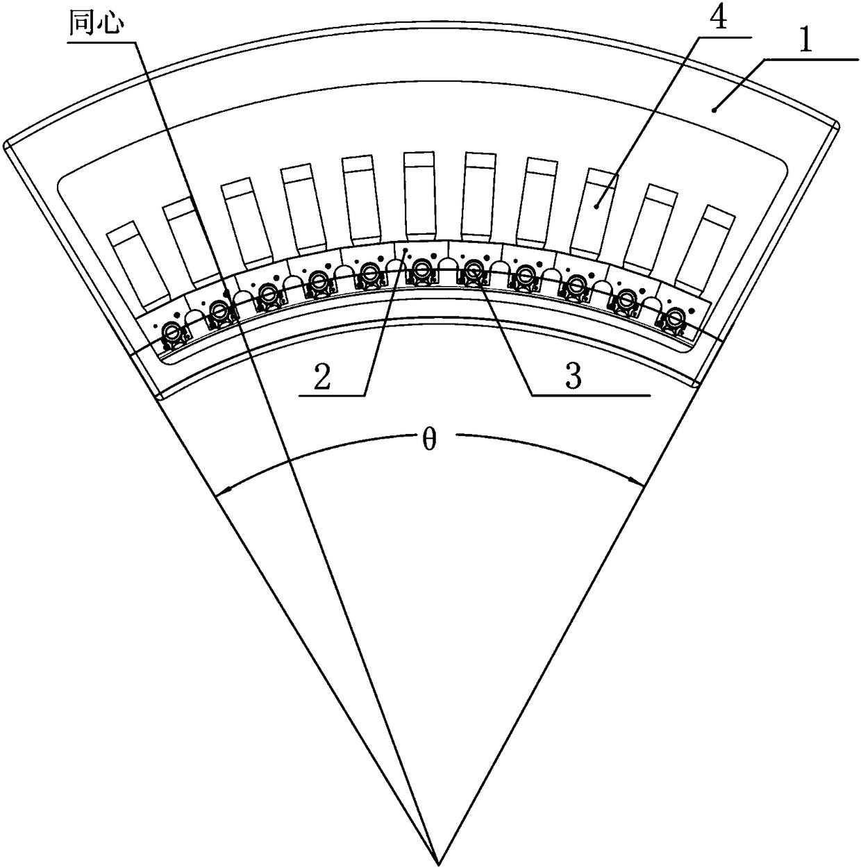
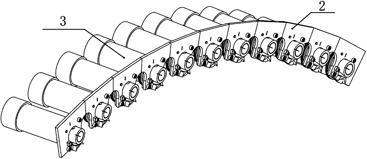
[0025] Such as figure 1 As shown, the arc-shaped multi-focus fixed anode grid-controlled ray source provided by the present invention includes an arc-shaped ray source housing 1 , a tube bracket 2 , multiple fixed anode reflective ray tubes 3 and multiple grid-controlled switches 4 . Among them, a plurality of fixed anode reflective ray tubes 3 are fixed on the arc-shaped ray source housing 1 through the ray tube bracket 2, and the focal points of the plurality of fixed anode reflective ray tubes 3 are distributed on the same distribution circle. Preferably, the plurality of fixed anode reflective ray tubes The focus of the reflective ray tube 3 is evenly distributed within a certain angle range α (360°≥α>0°) relative to the same distribution circle; a plurality of gate control switches 4 and a plurality of fixed anode ...


PUM


Abstract

The invention provides an arc-shaped multi-focus fixed anode gate controlled ray source which comprises an arc-shaped ray source shell, a ray tube bracket, a plurality of fixed anode reflected ray tubes and a plurality of gate controlled switches; the fixed anode reflected ray tubes are fixed on the arc-shaped ray source shell through the ray tube bracket; focuses of the fixed anode reflected raytubes are distributed on a same distribution circle; and the gate controlled switches are correspondingly connected with the fixed anode reflected ray tubes. The arc-shaped multi-focus fixed anode gate controlled ray source provided by the invention has the benefits that by splicing a plurality of arc-shaped multi-focus fixed anode gate controlled ray sources into a global ring structure, the focuses of all the fixed anode reflected ray tubes in the multi-focus fixed anode gate controlled ray sources can be distributed on the same distribution circle; and the arc-shaped multi-focus fixed anodegate controlled ray source is simple in structure and lower in cost and can generate rays with enough strength, and a sufficient number of focuses is distributed in the peripheral direction.

Description

technical field [0001] The invention relates to an X-ray source, in particular to an arc-shaped multi-focus fixed anode grid-controlled ray source. Background technique [0002] Static CT is a novel CT (Computed Tomography, computerized tomography) technical solution. Its overall structure is to use a full circle of detectors and a full circle of ray sources, and release the lines through the focal points of each ray source on the circumference in time sequence, so as to achieve The purpose of circular scanning is the same as that of spiral CT. Theoretically, this kind of static CT does not need rotating parts, so it does not need bearings and slip rings. It has a simple structure, fast theoretical circular scanning speed, and fast data transmission speed. [0003] At present, in the field of static CT, the current mainstream ideas for the whole-circle radiation source are as follows: 1. Using reflective discharge, the fixed anode of the whole ring cooperates with multiple ...

Claims


Application Information

Patent Timeline
IPC IPC(8): H01J35/02H01J35/04
CPCH01J35/02H01J35/045A61B6/4007H05G1/70A61B6/032H01J35/14H01J2235/062H01J35/025
Inventor 邢金辉崔志立高建曹红光
Owner NANOVISION TECHNOLOGY (BEIJING) CO LTD
Learn More