
Electronic equipment

A technology of electronic equipment and equipment, which is applied in the direction of TV, electrical components, color TV, etc., can solve problems such as unsmooth pop-up, friction and scratch, and resistance caused by pop-up

Active Publication Date: 2018-06-05
LENOVO (BEIJING) CO LTD
View PDF6 Cites 8 Cited by
  • Summary
  • Abstract
  • Description
  • Claims
  • Application Information

AI Technical Summary

Problems solved by technology

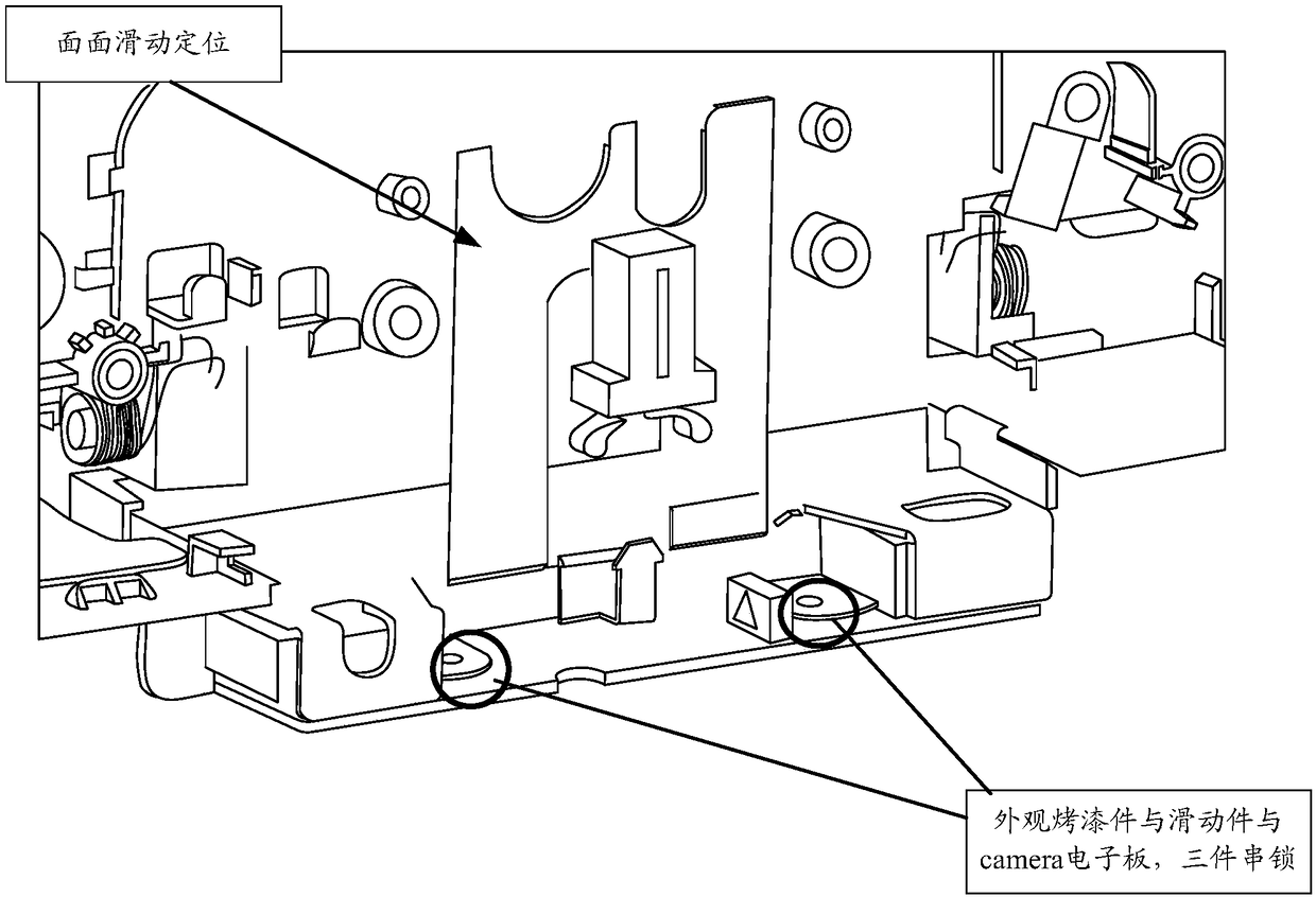
[0003] like figure 1 As shown, the push camera structure in the all-in-one machine is realized by surface-to-surface sliding positioning. The problem with this camera pop-up structure is: due to the excessive friction of the surface parts, the pop-up produces resistance, and it is necessary to refuel between the two parts. Solve the problem of unsmooth ejection, and at the same time, there will be friction and scratches in the middle of the appearance parts due to deformation problems
The pressing feel of this method is not good, and the damping feeling is not good.
In addition, the exterior painted parts and sliding parts are interlocked with the three parts of the Camera electronic board. If the camera fails, the Camera electronic board needs to be replaced when checking the fault, which is extremely inconvenient and laborious.

Method used


Image

  • Electronic equipment
  • Electronic equipment
  • Electronic equipment

Examples


Embodiment Construction

[0041] In order to understand the characteristics and technical contents of the embodiments of the present invention in more detail, the implementation of the embodiments of the present invention will be described in detail below in conjunction with the accompanying drawings. The attached drawings are only for reference and description, and are not intended to limit the embodiments of the present invention.

[0042] Figure 4 It is a schematic diagram of the structure and composition of the electronic equipment of the embodiment of the present invention Figure 1 ,Such as Figure 4 As shown, the electronic device includes: a camera module 11, a pop-up structure 12, and a device body 13, the camera module 11 is connected to the pop-up structure 12, wherein,

[0043] The pop-up structure 12 includes: a buckle 121, an elastic member 122, the first end of the elastic member 122 is fixed on the device body 13, and the second end of the elastic member 122 is in contact with the cam...


PUM


Abstract

The invention discloses electronic equipment which comprises a camera module, a pop-up structure and an equipment body, wherein the camera module is connected with the pop-up structure; the pop-up structure comprises a buckle and an elastic piece; pressing force applied to the camera module is used for pushing the pop-up structure to move along a first direction; the buckle in the pop-up structuremoves to a first position corresponding to the equipment body and is in a locked state, so that the camera module is in a pop-down state relative to the equipment body; the pressing force applied tothe camera module pushes the pop-up structure to move along the first direction, so that the buckle in the pop-up structure is in an unlocked state; and the elastic piece in the pop-up structure pushes the camera module to move along a second direction, so that the camera module is in a pop-up state relative to the equipment body.

Description

technical field [0001] The invention relates to a pop-up structure of a camera, in particular to an electronic device related to the pop-up structure of a camera. Background technique [0002] An all-in-one desktop (abbreviated as an all-in-one) refers to the integration of the host computer of a traditional split desktop into a display. Under the requirements of the appearance of the all-in-one machine, the camera has two states, one is hidden inside the whole machine when not in use, and the other is popped out of the whole machine when in use. The camera pop-up (Push Camera) structure can realize the pop-up of the camera, and the user can push the camera module (Camera module) from the inside of the whole machine by pressing the external surface. [0003] Such as figure 1 As shown, the push camera structure in the all-in-one machine is realized by surface-to-surface sliding positioning. The problem with this camera pop-up structure is: due to the excessive friction of t...

Claims


Application Information

Patent Timeline
IPC IPC(8): H04N5/225
CPCH04N23/57H04N23/00
Inventor 戴依含郝京阳
Owner LENOVO (BEIJING) CO LTD
Learn More