
Fixing box for automatic monitoring device of low-voltage distribution network

An automatic monitoring and low-voltage distribution network technology, which is applied in circuit devices, battery circuit devices, electric vehicles, etc., can solve the problems of hidden safety hazards in distribution networks, short battery life, simple structure, etc., to improve battery life stability, Improve adaptability and improve the effect of monitoring timeliness

Inactive Publication Date: 2018-06-05
浙江叶尼塞电气有限公司
View PDF6 Cites 0 Cited by
  • Summary
  • Abstract
  • Description
  • Claims
  • Application Information

AI Technical Summary

Problems solved by technology

[0003] When the distribution network passes through the forest area prone to wildfires, in order to strengthen the supervision of the power grid, it is usually necessary to install monitoring devices on the distribution network. Changeable weather, moreover, when the monitoring device is working, the electric energy on the distribution network is directly used, causing hidden dangers to the safety of the distribution network. In addition, the existing monitoring device has no backup power supply and the battery life is short

Method used


Image

  • Fixing box for automatic monitoring device of low-voltage distribution network
  • Fixing box for automatic monitoring device of low-voltage distribution network
  • Fixing box for automatic monitoring device of low-voltage distribution network

Examples


Embodiment Construction

[0023] The following will clearly and completely describe the technical solutions in the embodiments of the present invention with reference to the accompanying drawings in the embodiments of the present invention. Obviously, the described embodiments are only some, not all, embodiments of the present invention. Based on the embodiments of the present invention, all other embodiments obtained by persons of ordinary skill in the art without making creative efforts belong to the protection scope of the present invention.

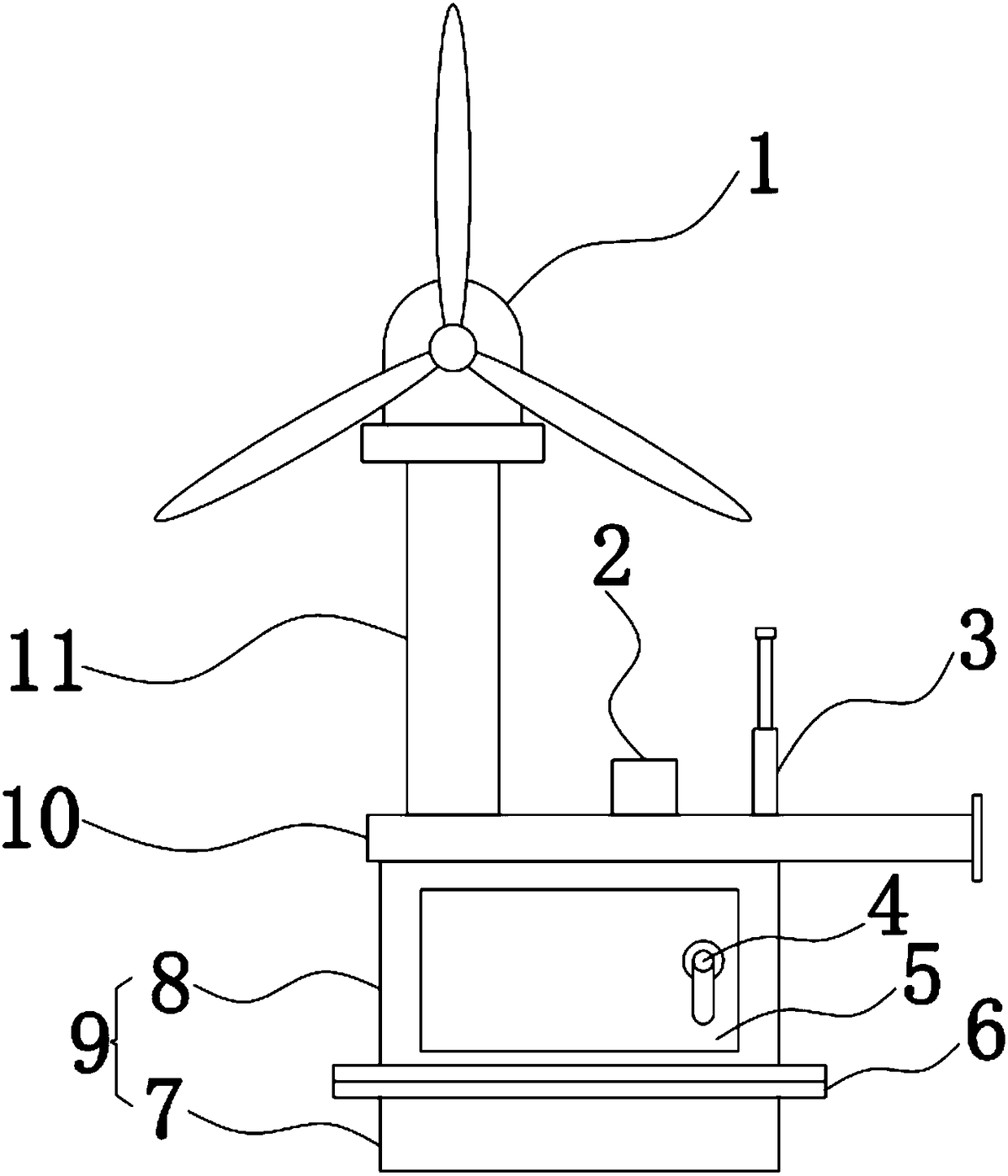
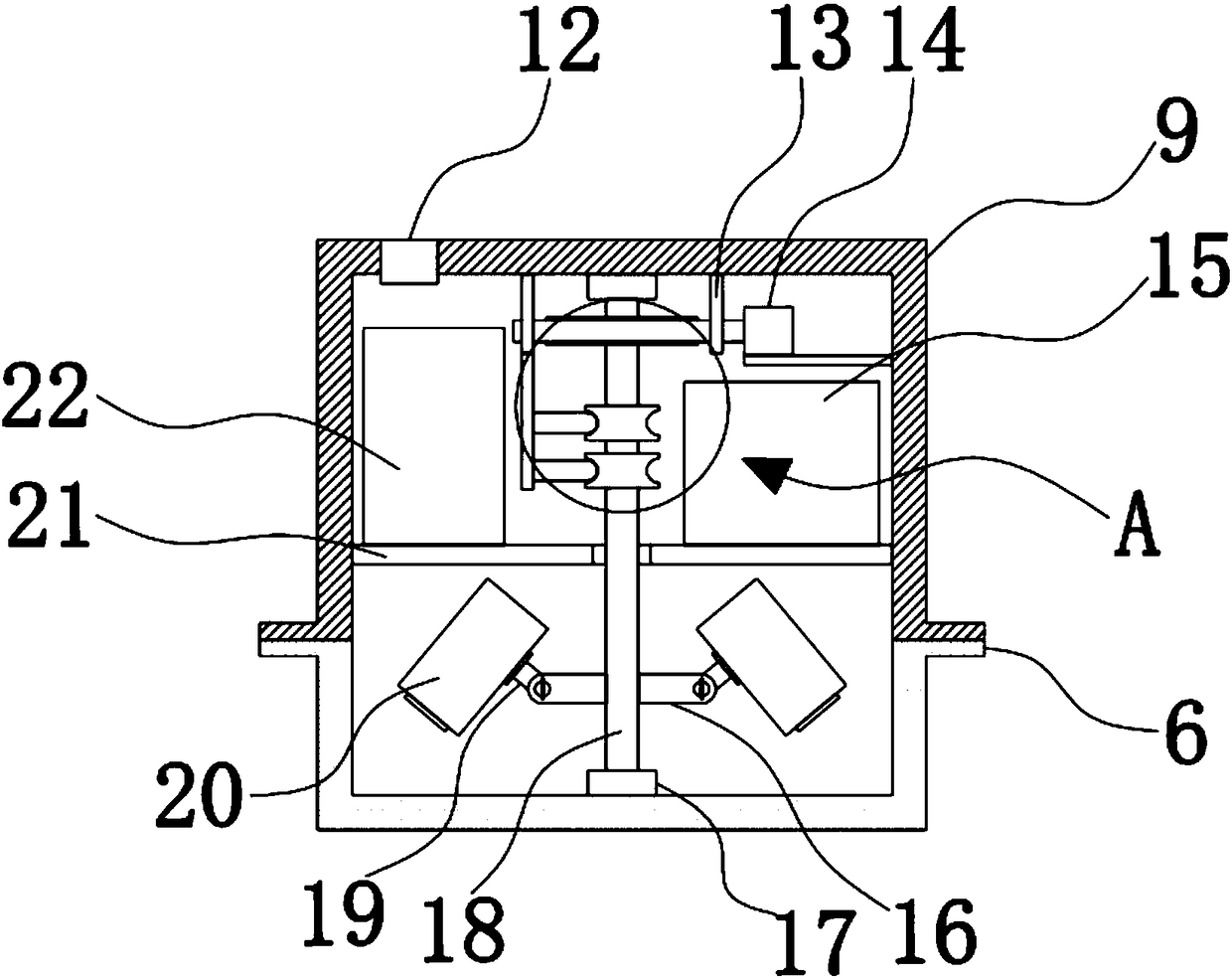
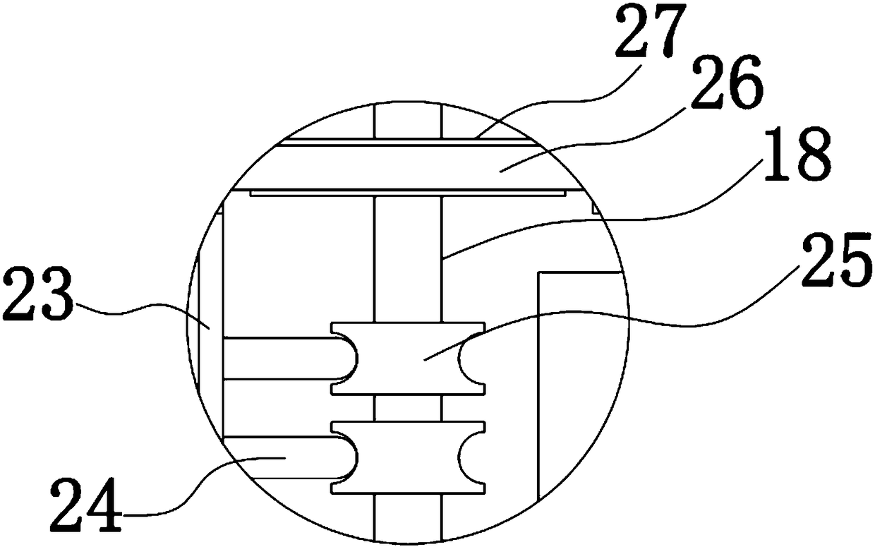
[0024] like Figure 1-4 As shown, a fixed box for a low-voltage distribution network automation monitoring device, including:

[0025] Mounting arm 10, the upper side of described mounting arm 10 is fixedly connected with supporting column 11, and the top of described supporting column 11 is installed with wind power generator 1, and sensor module 2 and signal transmitting module are also fixed on described mounting arm 10. Group 3;

[0026] Fixed box body 9...


PUM


Abstract

The invention discloses a fixing box for an automatic monitoring device of a low-voltage distribution network. The fixing box comprises a mounting arm, wherein a supporting column is fixedly connectedto the upper side of the mounting arm, a wind generator is installed at the top of the supporting column, and a sensor module and a signal transmission module are also fixed to the mounting arm; a fixing box main body, wherein a division plate is fixedly connected in the fixing box main body, a power supply I and a power supply II are fixed to the division plate, a rotating rod is arranged in thefixing box main body, a turbine is fixed to the rotating rod, and a worm is engaged with the turbine; and an electric sliding ring, wherein the electric sliding ring is fixed to the rotating rod, theelectric sliding ring is in sliding connection with an electric brush, the electric brush is fixed to an elastic rod, a fixing rod is also fixed to the rotating rod, an adjusting rod is rotationallyconnected to the fixing rod, and a camera is installed on the adjusting rod. The fixing box disclosed by the invention ensures stable endurance by wind power generation and has high adaptability; anda monitoring image at the lower side is captured all around, monitoring data are obtained in time, and the monitoring timeliness is improved.

Description

technical field [0001] The invention belongs to the technical field of power grid monitoring devices, and in particular relates to a fixed box for a low-voltage distribution network automation monitoring device. Background technique [0002] The distribution network is composed of overhead lines, cables, towers, distribution transformers, isolating switches, reactive power compensators and some auxiliary facilities, etc., and plays an important role in distributing electric energy in the power network. According to the voltage level, the distribution network can be divided into high-voltage distribution network (35-110KV), medium-voltage distribution network (6-10KV, 20KV in Suzhou), and low-voltage distribution network (220 / 380V); In large super-large cities, the 220KV power grid also has power distribution functions. Classified according to the function of the power supply area, it can be divided into urban distribution network, rural distribution network and factory dist...

Claims


Application Information

Patent Timeline
Patent Type & Authority Applications(China)
IPC IPC(8): H04N7/18H04N5/225G08C17/02H02J7/14F16M11/06F16M11/18G01D21/02
CPCH02J7/1423H04N7/18G08C17/02F16M11/06F16M11/18G01D21/02H04N23/51
Inventor 卢博朗
Owner 浙江叶尼塞电气有限公司
Learn More