
Movable/rotatable/storable oil can

An oil pot, an integrated technology, applied in the field of kitchen utensils, can solve the problems of difficult to meet various needs, single and widespread use, etc.

Pending Publication Date: 2018-06-08
邹洤 +1
View PDF1 Cites 0 Cited by
  • Summary
  • Abstract
  • Description
  • Claims
  • Application Information

AI Technical Summary

Problems solved by technology

[0006] CN200975728Y (2007.11.14) discloses a range hood capable of adding water and refueling. The range hood is provided with an oil storage tank on the top surface of the body. And it is fixed and not widely used, so far it has been difficult to meet the various needs of people's daily life. Therefore, it is necessary to further improve and perfect

Method used


Image

  • Movable/rotatable/storable oil can
  • Movable/rotatable/storable oil can
  • Movable/rotatable/storable oil can

Examples


Embodiment 1

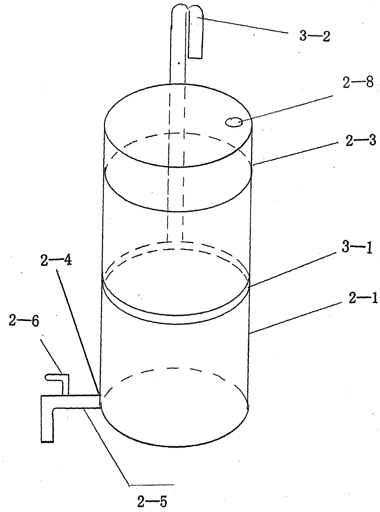
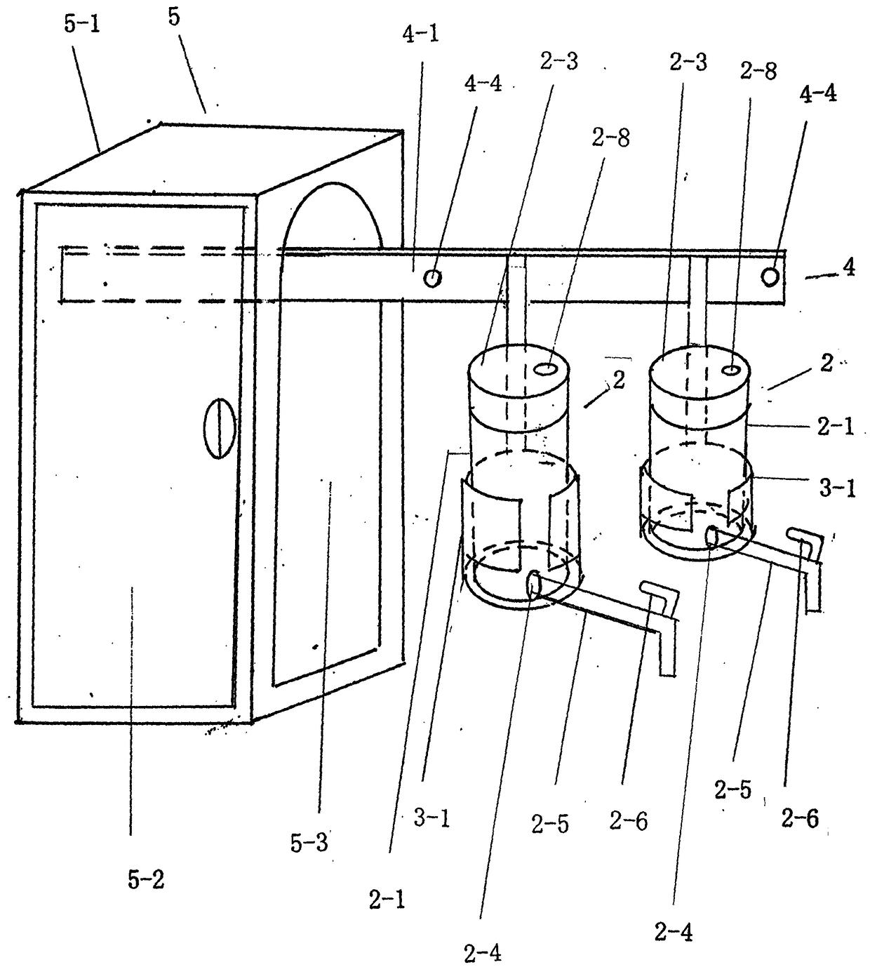
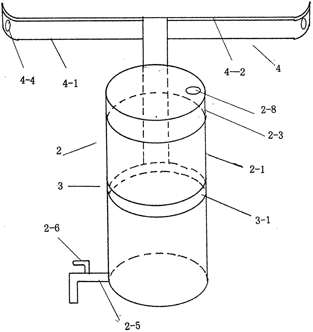
[0089]By adopting prior art, a track 4 is fixedly arranged on the wall above the cooking utensils used for cooking dishes and meals by two post track piles 4-3, four connecting devices 4-4 or fixed, moving object surface and connected with kettle cabinet 5 To connect, two oil pots 2, one large and one small, are connected with the track 4 under the load of corresponding two pot holders 3, one large and one small, and the two oil pots 2, one large and one small, are connected to the track 4 under the load of two pot holders 3, one large and one small. Under the load, the access to and out of the pot cabinet 5 is realized sequentially through the track 4, wherein, two oil pots 2, one large and one small, are equipped with an oil pot main body 2-1, a pot cover 2-3, an oil pipe docking port 2-4, and an oil pipe 2 -5, faucet 2-6, oil pot main body 2-1 upper end face spout 2-2, pot cover 2-3 upper end face air vent 2-8; two pot supports 3, one large and one small, are all provided wi...

Embodiment 2

[0093] By adopting the existing technology, a track 4, two track piles 4-3, four connecting devices 4-4 are connected and combined with the range hood body 6, wherein the track main body 4-1, the track pile 4- 3 and the exhaust (suction) range hood body 6 are initially set as one, to achieve fixed connection, or, according to the different needs of users, install and realize the track main body 4-1, track pile 4-3, and connecting device 4-4 Combination with the connection of the smoker (suction) range hood body 6, and then realize the suction (suction) range hood body 6 of at least one track 4, at least one pot holder 3, and at least one oil pot (see attached Figure 16 ).

Embodiment 3

[0095] By adopting the prior art, a track 4, two column track piles 4-3, four connection devices 4-4 are connected and combined with various stove bodies 7 such as gas stoves and electromagnetic stoves, wherein the track main body 4-1, the track The pile 4-3 is initially set as one with various stove bodies 7 such as gas stoves and electromagnetic stoves to realize a fixed connection, or it can be set according to the different needs of users and realize the track main body 4-1 and the track pile 4-3 , the connecting device 4-4 and various types of stove body 7 such as gas stoves, electromagnetic stoves, etc. Stove body 7 (see attached Figure 17 ).


PUM


Abstract

The invention relates to an oil can, in particular to a movable / rotatable / storable type oil can. The movable / rotary / storable type oil can comprises an oil can part, a can support, a track and a can cabinet, and is characterized in that the oil can part is connected and combined with the can support, the track and the can cabinet so as to realize the functions of self movement, rotation and storage; the 'four-in-one' connecting combination of the oil can, the can support, the track and the can cabinet is adopted, or the 'three-in-one' connecting combination of the oil can, the can support and the track is subject to initial integrated connection with a range hood, a gas stove, a fixed or movable bracket and a cupboard through the prior art, or the connection combination is selected according to actual requirements, so that the traditional food cooking oil use mode is changed, the food cooking edible oil process is simplified, and the life quality of people is favorably improved.

Description

technical field [0001] The invention relates to a kitchen utensil, in particular to a movable / rotating / storage oil pot. Background technique [0002] Pot (foreign name Pot), a utensil with a handle and a mouth made of ceramics or metal, usually used to hold liquids such as water, wine, oil, etc., has a history of thousands of years. [0003] The oil pot belongs to the kitchen utensils generally recognized by all countries in the world. It is a utensil for storing edible oil and providing edible oil for international cooking methods such as stir-frying, frying, and stewing. opened daily necessities or household appliances. [0004] Up to now, the types of oil pots and the materials used can be said to be various and innumerable, and they have gradually beautified people's daily life. When using edible oil in the place where cooking dishes are cooked, it is generally necessary to go to the cabinet, open the door of the cabinet, take out the oil pot from the cabinet, walk to ...

Claims


Application Information

Patent Timeline
IPC IPC(8): A47J47/01A47J47/02
CPCA47J47/01A47J47/02
Inventor 邹洤邹建东
Owner 邹洤
Learn More