Energy storage welding machine control system

A control system and energy storage welding machine technology, applied in the direction of manufacturing tools, welding equipment, arc welding equipment, etc., can solve the problem of inability to accurately control the three-phase rectifier thyristor, large demand for power grid capacity, and poor control accuracy Advanced problems, to achieve the effect of shortening the charging time, less quantity, and good system stability

Pending Publication Date: 2018-06-08
HERON INTELLIGENT EQUIP CO LTD
View PDF0 Cites 2 Cited by
  • Summary
  • Abstract
  • Description
  • Claims
  • Application Information

AI Technical Summary

Problems solved by technology

[0003] This method uses PLC as the main controller, and the scanning period is long, and it is impossible to accurately control the conduction angle of the three-phase rectifier thyristor in each half-wave, and the control accuracy is not high, and this method has a great demand for the network capacity of the power grid. Big and takes a long time to charge

Method used


Image

  • Energy storage welding machine control system
  • Energy storage welding machine control system
  • Energy storage welding machine control system

Examples


Embodiment Construction

[0026] In order to make the purpose, technical solutions and advantages of the embodiments of the present invention clearer, the technical solutions in the embodiments of the present invention will be clearly and completely described below in conjunction with the drawings in the embodiments of the present invention. Obviously, the described embodiments It is a part of embodiments of the present invention, but not all embodiments. The components of the embodiments of the invention generally described and illustrated in the figures herein may be arranged and designed in a variety of different configurations.

[0027] Accordingly, the following detailed description of the embodiments of the invention provided in the accompanying drawings is not intended to limit the scope of the claimed invention, but merely represents selected embodiments of the invention. Based on the embodiments of the present invention, all other embodiments obtained by persons of ordinary skill in the art wi...


PUM


Abstract

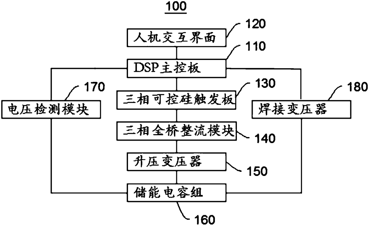
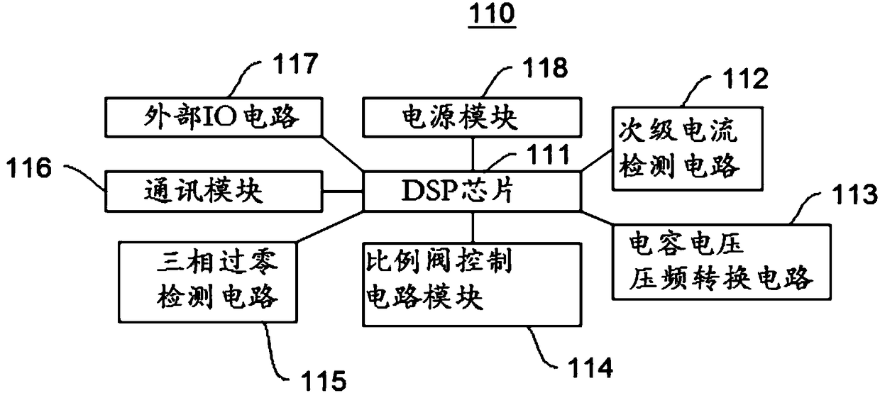
The invention provides an energy storage welding machine control system and relates to the technical field of welding machines. The energy storage welding machine control system comprises a DSP main control board, a three-phase thyristor trigger board, a three-phase full-bridge rectifier module, a step-up transformer, an energy storage capacitor group, a voltage detection module and a welding transformer. The step-up transformer boosts the input three-phase alternating current. The three-phase thyristor trigger board triggers the three-phase full-bridge rectifier module under a control commandof the DSP main control board. The three-phase full-bridge rectifier module rectifies the boosted alternating current to the direct current, and the direct current is used for charging the energy storage capacitor group. The voltage detection module detects the voltage of the energy storage capacitor group in real time. When the voltage reaches the preset voltage, the three-phase full-bridge rectifier module is switched to a single-phase rectification working mode to reduce the charging current of the energy storage capacitor group. According to the energy storage welding machine control system, the number of the modules is small, the charging voltage is more accurate, and the system stability is good.

Description

technical field [0001] The invention relates to the technical field of welding machines, in particular to a control system for energy storage welding machines. Background technique [0002] In the prior art, it is composed of PLC, three-phase intelligent charging module, voltage detection board, and current detection board. The welding voltage value is set through the touch screen, and then the PLC calculates the analog voltage value required by the three-phase intelligent module, and outputs the voltage The three-phase intelligent charging module controls the switching on and off of the thyristor to charge the capacitor. When the PLC sends the charging signal to the three-phase module, it continuously detects the real-time voltage on the capacitor, feeds back the voltage result once every 10ms, and controls the analog voltage value according to the feedback voltage value to adjust the charging current and speed. [0003] This method uses PLC as the main controller, and the...

Claims


Application Information

Patent Timeline
Patent Type & Authority Applications(China)
IPC IPC(8): B23K9/10
CPCB23K9/1081
Inventor 艾俊
Owner HERON INTELLIGENT EQUIP CO LTD
Why Eureka
Try Eureka