Cooling system for new energy automobile

A new energy vehicle and heat dissipation system technology, which is applied in the field of new energy vehicle heat dissipation devices, can solve problems such as insufficient stability, aging of electrical appliances, electric lines, and insufficient convenience and communication of heat dissipation system regulation, so as to achieve easy adjustment, easy heat dissipation, and prevent line aging and the effect of burning electrical appliances

Inactive Publication Date: 2018-06-08
DONGGUAN XIANGFEI INTELLIGENT EQUIP TECH CO LTD
View PDF0 Cites 1 Cited by
  • Summary
  • Abstract
  • Description
  • Claims
  • Application Information

AI Technical Summary

Problems solved by technology

[0004] The purpose of the present invention is to provide a heat dissipation system for new energy vehicles to solve the problem that the existing heat dissipation system proposed in the above-mentioned background technology is used because the electric circuit structure inside the new energy vehicle is relatively complicated. , it is impossible to properly cool down some wires and electrical appliances, which can easily lead to aging of electrical appliances and electrical circuits, thereby affecting the service life of the car, and the general cooling system is not convenient and stable when adjusting, and it is not stable enough. The adjustment mechanism makes the shock and vibration generated during the driving of the car very easy to cause damage to the engine parts of the car, which is an extremely dangerous problem

Method used


Image

  • Cooling system for new energy automobile
  • Cooling system for new energy automobile
  • Cooling system for new energy automobile

Examples


Embodiment Construction

[0026] The following will clearly and completely describe the technical solutions in the embodiments of the present invention with reference to the accompanying drawings in the embodiments of the present invention. Obviously, the described embodiments are only some, not all, embodiments of the present invention. Based on the embodiments of the present invention, all other embodiments obtained by persons of ordinary skill in the art without making creative efforts belong to the protection scope of the present invention.

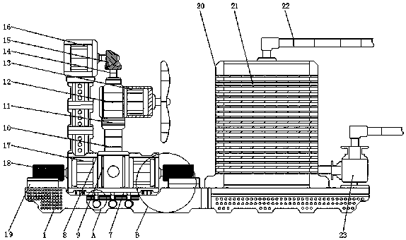
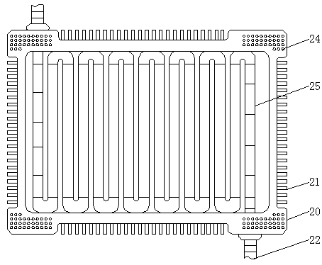
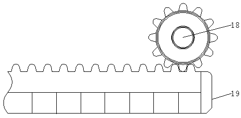
[0027] see Figure 1-5, the present invention provides a technical solution: a heat dissipation system for new energy vehicles, including a main body 1, a slideway 2, a sliding column 3, a middle receiving block 4, a side sliding block 5, a chute 6, a control mechanism 7, and a connecting frame 8 hydraulic cylinder 9, hydraulic rod 10, bearing 11, connecting seat 12, first motor 13, main bevel gear 14, auxiliary gear 15, second motor 16, third motor 17, spur g...


PUM


Abstract

The invention relates to a cooling system for a new energy automobile. The cooling system for the new energy automobile comprises a main body and a first electric motor; a slide way is arranged withinthe lower end of the main body; a slide column is placed at the inner end of the slide way; a regulating mechanism is mounted at the left upper end of the main body; a linking frame is fixed at the upper end of the regulating mechanism; and a hydraulic cylinder is mounted within the linking frame. The cooling system for the new energy automobile has the advantages that the sliding between the slide way and the slide column can be more stable through the sliding of the slide column with the octagonal structure in the slide way because the slide way and the slide column, a middle bearing block,a side slide block and a slide groove are arranged in the cooling system for the new energy automobile; therefore, the main body and the regulating mechanism stably slide; and meanwhile, the regulating mechanism is assisted to slide through the movable connection between the side slide block and the slide groove so that a purpose of sharing the gravity of the regulating mechanism is achieved, theregulation of the regulating mechanism in the horizontal direction is made convenient and a purpose of changing positions of the first electric motor and a fan is achieved.

Description

technical field [0001] The invention relates to the technical field of heat dissipation devices for new energy vehicles, in particular to a heat dissipation system for new energy vehicles. Background technique [0002] New energy vehicles refer to the use of unconventional vehicle fuels as the power source, comprehensive vehicle power control and advanced technology in driving, and the formation of vehicles with advanced technical principles, new technologies, and new structures, and vehicles are equipped with heat dissipation The system is generally used to dissipate heat from the engine and other mechanisms. [0003] When the existing heat dissipation system is in use, due to the complex structure of electrical circuits inside the new energy vehicle, the previous fixed heat dissipation system cannot properly cool down some wires and electrical appliances, which can easily lead to aging of electrical appliances and electrical circuits. As a result, the service life of the ...

Claims


Application Information

Patent Timeline
Patent Type & Authority Applications(China)
IPC IPC(8): B60K11/04
CPCB60K11/04
Inventor 邓凯谢海燕
Owner DONGGUAN XIANGFEI INTELLIGENT EQUIP TECH CO LTD
Why Eureka
Try Eureka