Optical fiber vibration event identification method based on adaptive mean de-threshold

A technology of optical fiber vibration and identification method, which is applied in the direction of instruments, measuring devices, and using wave/particle radiation, etc., can solve the problems of low alarm accuracy, change self-adaptation, and high system false alarm rate, so as to improve identification efficiency and accuracy Effect

Inactive Publication Date: 2018-06-08
光子瑞利科技(北京)有限公司
View PDF3 Cites 17 Cited by
  • Summary
  • Abstract
  • Description
  • Claims
  • Application Information

AI Technical Summary

Problems solved by technology

[0003] However, due to the high sensitivity of φ-OTDR and the influence of polarization fading in the fiber, the system false alarm rate is high
The existing optical fiber vibration source identification methods usually use fixed threshold filtering, which cannot adapt to changes in the external environment, and the alarm accuracy is low

Method used


Image

  • Optical fiber vibration event identification method based on adaptive mean de-threshold
  • Optical fiber vibration event identification method based on adaptive mean de-threshold
  • Optical fiber vibration event identification method based on adaptive mean de-threshold

Examples


Embodiment Construction

[0019] In the following description, for purposes of illustration rather than limitation, specific details, such as specific system architectures, interfaces, and techniques, are set forth in order to provide a thorough understanding of the present application. It will be apparent, however, to one skilled in the art that the present application may be practiced in other embodiments without these specific details. In other instances, detailed descriptions of well-known devices, circuits, and methods are omitted so as not to obscure the description of the present application with unnecessary detail.

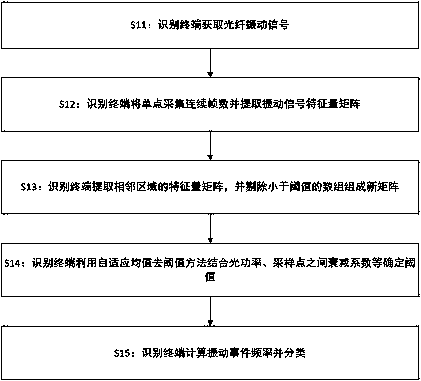
[0020] see figure 1 , a flow chart of an embodiment of an optical fiber vibration source identification method of the present invention, the method includes:

[0021] S11: Identify the terminal to acquire the optical fiber vibration signal.

[0022] Wherein, the optical fiber vibration signal is a digital signal of the optical fiber vibration source, and the optical fiber electri...


PUM


Abstract

The invention discloses an optical fiber vibration source identification method, device and system. The method comprises the following steps: obtaining optical fiber vibration signals through an identification terminal; and carrying out classification on the optical fiber vibration signals through an adaptive mean de-threshold algorithm to obtain a vibration source type of the optical fiber vibration signals. Through the mode above, the method can realize intelligent identification of optical fiber vibration sources and correct classification of the vibration source information.

Description

technical field [0001] The invention relates to the field of optical fiber communication, in particular to an optical fiber vibration source identification method, device and system. Background technique [0002] The distributed optical fiber vibration sensing system has the characteristics of anti-electromagnetic interference, good electrical insulation, corrosion resistance, high sensitivity, and can realize a wide range of perimeter monitoring, and the sensing optical fiber can be buried underground, which has good concealment. It can be used to monitor and protect important areas and places such as national borders, military bases, power plants, oil pipelines, nuclear facilities and prisons. When the detection optical fiber is affected by external interference and vibrates, some characteristics of the transmitted light in the optical fiber will change. The identification terminal collects the signal, analyzes the characteristics of the collected signal to judge the chang...

Claims


Application Information

Patent Timeline
Patent Type & Authority Applications(China)
IPC IPC(8): G01H9/00
CPCG01H9/004
Inventor 李建彬刘浩宇魏照柴军杰魏嘉刘本刚
Owner 光子瑞利科技(北京)有限公司
Why Eureka
Try Eureka