

Optical system with optimized low-light effects
An optical system and optical axis technology, applied in the field of optical systems, can solve the problems of inability to achieve the same level of resolution, large performance loss, cost pressure, etc., and achieve the effects of rich color detail information, high picture illumination, and high resolution level.
- Summary
- Abstract
- Description
- Claims
- Application Information
AI Technical Summary
Problems solved by technology
Method used
Image

Examples
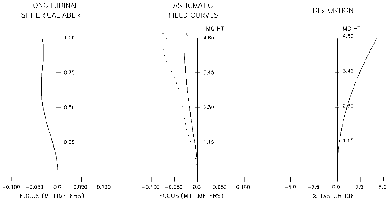
Embodiment 1
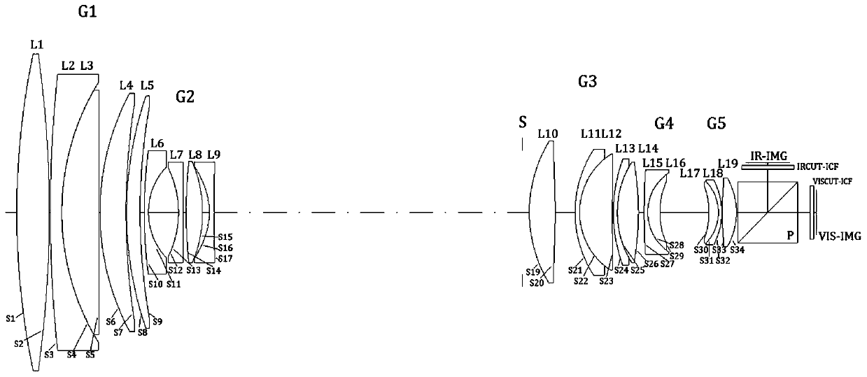
[0026] Such as figure 1 As shown, this embodiment includes the first lens group G1 with positive refractive power, the second lens group G2 with negative refractive power, the aperture stop S of the system, and the second lens group with positive refractive power from the object side to the image side. Three lens groups G3, fourth lens group G4 with negative refractive power, fifth lens group G5 with positive refractive power, dual-spectrum photosensitive mechanism including dichroic prism P, infrared sensor IR-IMG and visible light sensor VIS-IMG.
[0027] The ratio of the focal length of the telephoto end of the lens of the first lens group G1 to the focal length of the lens group is (1.40, 4.25), and the focal length of the first lens on the near object side in the first lens group G1 is equal to the focal length of the lens telephoto end The ratio of the focal length is (-0.48,-0.23).
[0028] The ratio of the focal length of the first lens on the near-object side in the ...
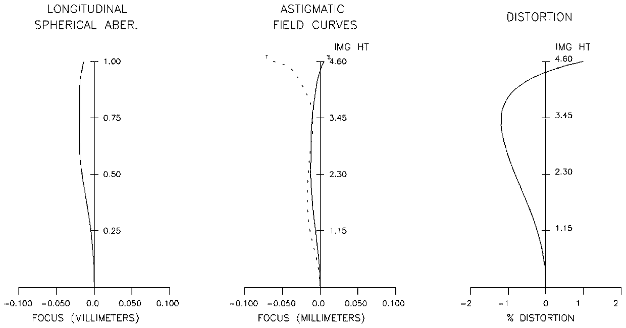
Embodiment 2
[0062] The difference with Embodiment 1 is that in this embodiment:
[0063] The second lens group G2 includes in order from the object side: the sixth lens L6 with negative refractive power, the seventh lens L7 with negative refractive power and both sides are aspherical, and the eighth lens with positive refractive power L8 and the ninth lens L9 with negative power and aspheric surfaces on both sides.
[0064] The third lens group G3 includes in order from the object side: the tenth lens L10 with positive refractive power and both surfaces are aspherical, the eleventh lens L11 with negative refractive power, and the twelfth lens L11 with positive refractive power. Lens L12, the thirteenth lens L13 with negative refractive power and the fourteenth lens L14 with positive refractive power, wherein the eleventh lens L11 and the twelfth lens L12, the thirteenth lens L13 and the fourteenth lens L14 glued together.
[0065] Various numerical data about the zoom lens of Example 2 ...
PUM
| Property | Measurement | Unit |
|---|---|---|
| refractive index | aaaaa | aaaaa |
| Abbe number | aaaaa | aaaaa |
| refractive index | aaaaa | aaaaa |
Abstract
Description
Claims
Application Information