Check patentability & draft patents in minutes with Patsnap Eureka AI!

Reverse plug connector and manufacturing method thereof

A technology of positive and negative plug-in connectors and contact parts, which is applied in the direction of contact manufacturing, connection, contact box/base manufacturing, etc. It can solve problems such as easy water seepage, insufficient bonding of injection molding materials, and increased manufacturing costs. Injection times, prevent water seepage, reduce the effect of collection gap

Active Publication Date: 2020-06-16
SHENZHEN EVERWIN PRECISION TECH
View PDF3 Cites 1 Cited by
  • Summary
  • Abstract
  • Description
  • Claims
  • Application Information

AI Technical Summary

Problems solved by technology

[0003] The increase in the number of injection molding will inevitably lead to an increase in manufacturing costs. At the same time, the injection materials of each injection are layered and superimposed, resulting in insufficient bonding of injection materials of different times, and easy to seep water

Method used


Image

  • Reverse plug connector and manufacturing method thereof
  • Reverse plug connector and manufacturing method thereof
  • Reverse plug connector and manufacturing method thereof

Examples


Embodiment Construction

[0032] In order to make the purpose, technical solution and advantages of the present application clearer, the technical solution of the present application will be clearly and completely described below in conjunction with specific embodiments of the present application and corresponding drawings. Apparently, the described embodiments are only some of the embodiments of the present application, rather than all the embodiments. Based on the embodiments in this application, all other embodiments obtained by persons of ordinary skill in the art without making creative efforts belong to the scope of protection of this application.

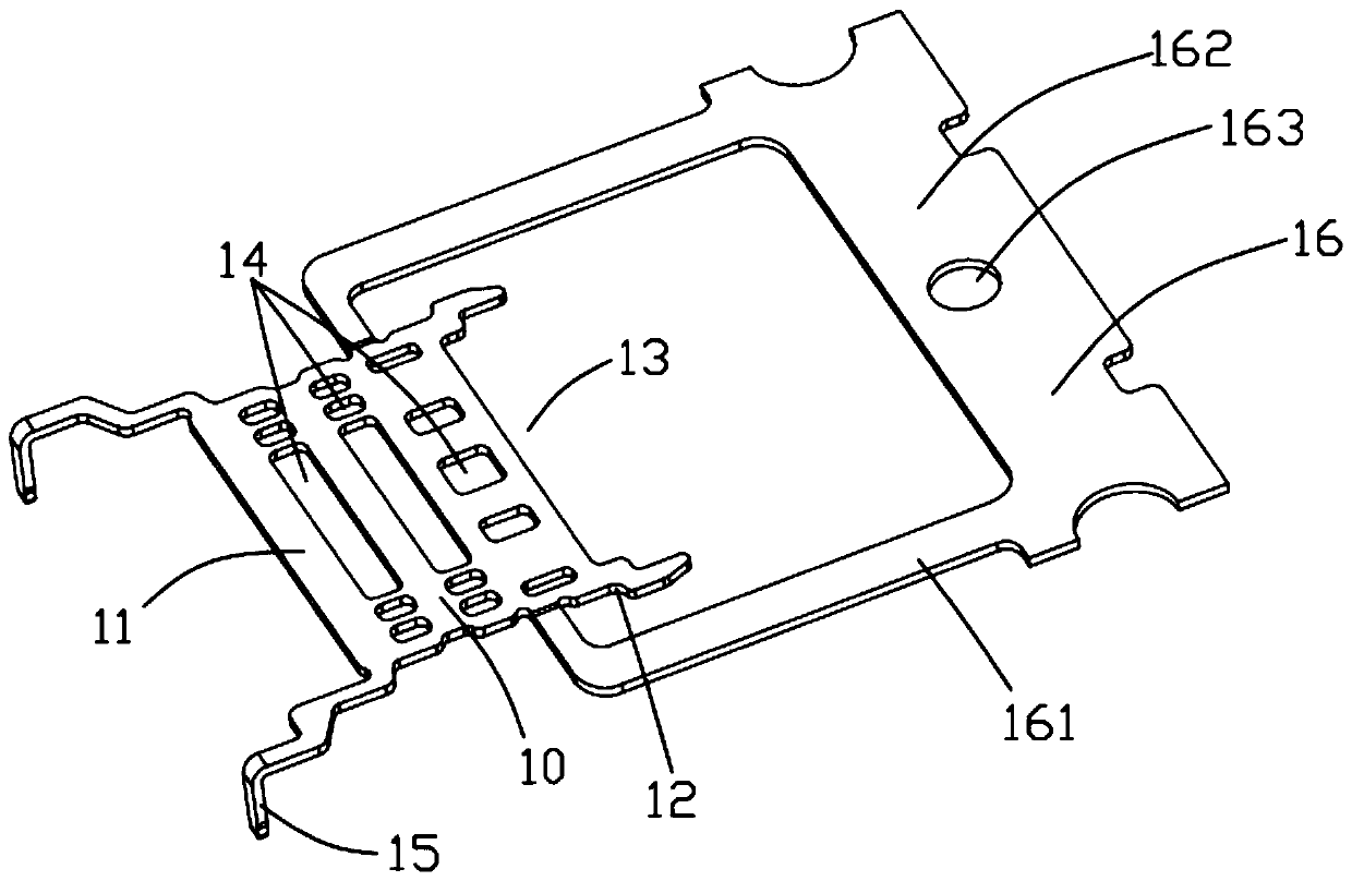
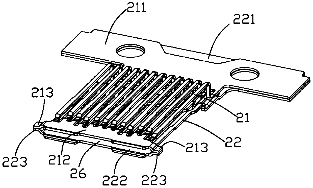
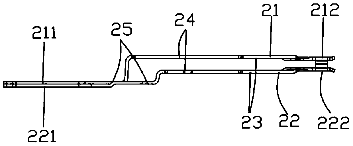
[0033] see Figure 8 , Figure 9 As shown, the forward and reverse plug connector of the present application includes first and second terminal groups 21, 22, a metal partition 10 located between the first and second terminal groups 21, 22 and electrically isolated from each other, and the The first and second terminal groups 21 , 22 are integrally ...


PUM


Abstract

A connector capable of positively and reversely plugging comprises a metal partition plate, a first terminal group, a second terminal group, an internal insulator and an external insulator, wherein the first terminal group and the second terminal group are arranged at an upper side and a lower side of the metal partition plate, the internal insulator is used for integrally forming the metal partition plate, the first terminal group and the second terminal group, and the external insulator is formed outside the internal insulator. The invention also provides a manufacturing method of the connector capable of positively and reversely plugging.

Description

technical field [0001] The present application relates to the field of electrical connectors, in particular to a reversible plug-in connector and a manufacturing method thereof. Background technique [0002] The Type C socket adopts a completely symmetrical conductive terminal design with upper and lower double layers, which supports plugs to be inserted in both directions, which improves the user's use effect. on three sides. In injection molding, it is generally necessary to use multiple injection molding methods to complete the production, and the most common method is to perform three-time injection molding. [0003] The increase in the number of injection molding times will inevitably lead to an increase in manufacturing costs. At the same time, the materials for each injection molding are superimposed in layers, resulting in insufficient bonding between the injection molding materials of different times and easy water seepage. Contents of the invention [0004] In ...

Claims


Application Information

Patent Timeline
Patent Type & Authority Patents(China)
IPC IPC(8): H01R13/02H01R13/405H01R13/504H01R43/16H01R43/18H01R43/24
CPCH01R13/02H01R13/405H01R13/504H01R43/16H01R43/18H01R43/24
Inventor 张秀华
Owner SHENZHEN EVERWIN PRECISION TECH
Features
  • R&D
  • Intellectual Property
  • Life Sciences
  • Materials
  • Tech Scout
  • Unparalleled Data Quality
  • Higher Quality Content
  • 60% Fewer Hallucinations
Learn More