
Pin inserting mechanism and pin inserting method for inserting four different mould pins into pin terminals

A pin terminal and pin technology, which is applied in the assembly/disassembly of contacts, manufacturing of contacts, etc., can solve the problems of low operation efficiency, difficulty in efficiency and quality control, and difficulty in effectively reducing labor costs.

Pending Publication Date: 2018-06-08
HANGZHOU TAISHANG MACHINERY CO LTD
View PDF0 Cites 9 Cited by
  • Summary
  • Abstract
  • Description
  • Claims
  • Application Information

AI Technical Summary

Problems solved by technology

[0003] The present invention solves the problem of low manufacturing operation efficiency, time-consuming and labor-intensive, low assembly precision, and difficult effective control of product quality that exist in existing automotive sensors such as inserting different molding die pins into pin terminals; Auxiliary to improve production quality and efficiency, it is difficult to really effectively improve the efficiency and quality control in the production and assembly process, the manufacturing cost is high, and the labor cost is difficult to effectively reduce the status quo and provide a method that can automatically complete the molding and insertion of four different model pins into the pins In the terminal, improve the efficiency of production operation, save time and labor, high efficiency, high assembly precision, better control, improve product quality, reduce manufacturing labor costs, and reduce the overall manufacturing cost. Insert four different mold pins into the pin terminal. Mechanism and pin insertion method

Method used


Image

  • Pin inserting mechanism and pin inserting method for inserting four different mould pins into pin terminals
  • Pin inserting mechanism and pin inserting method for inserting four different mould pins into pin terminals
  • Pin inserting mechanism and pin inserting method for inserting four different mould pins into pin terminals

Examples


Embodiment 1

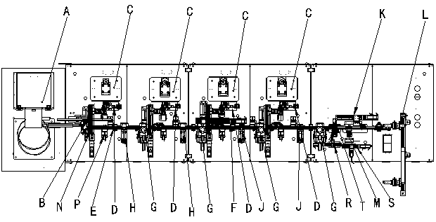
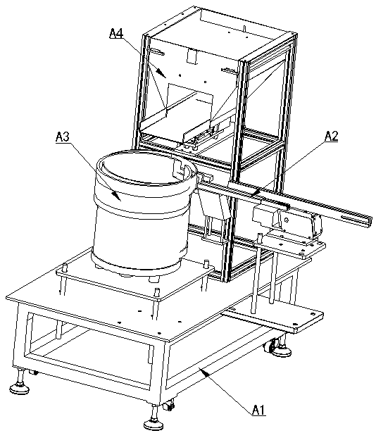
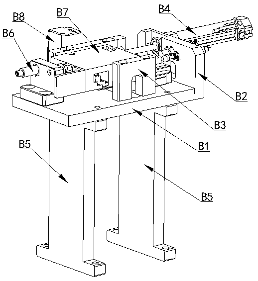
[0053] figure 1 , figure 2 , image 3 , Figure 4 , Figure 5 , Figure 6 , Figure 7 , Figure 8 , Figure 9 , Figure 10 , Figure 11 , Figure 12 , Figure 13 , Figure 14 , Figure 15 , Figure 16 , Figure 17 , Figure 18 In the shown embodiment, a pin insertion mechanism for inserting four different die pins into the pin terminals includes a main conveying line, a feeding mechanism A, a first material shifting mechanism B, and four different mold materials for forming die pins Forming mechanism C, continuous material cutting mechanism D, material transfer pin assembly N, positioning mechanism P, transfer mechanism E, second material shifting mechanism F, pressing mechanism, material cutting mechanism G, high and low needle detection device R, visual inspection Device S, high and low needle detection and visual detection device T, discharge transfer mechanism K and unloading mechanism L, the first shifting mechanism B is connected with the feeding mechan...

Embodiment 2

[0055] A pin insertion method for inserting four different die pins into a pin terminal, comprising the following steps

[0056] a. Generally, the feeding mechanism in Embodiment 1 sends the pin terminals to the pin terminal feeding step of the first material shifting mechanism described in one of claims 1 to 9;

[0057] b. Feed the entire mold straight pin from the back of the first molding needle mold material forming mechanism in the four different molding needle mold material forming mechanisms of embodiment 1 into the first forming mold needle mold material forming mechanism, hydraulic pressure The first mold pin forming step in which the booster cylinder is pressed down;

[0058] c. After the first type of mold pin is pressed and formed, continue to feed the material forward, and transport the formed first type of mold pin to the continuous material cutting mechanism of Example 1, and the cutting knife takes the first type of mold pin material Cut off the separate conti...


PUM


Abstract

The invention discloses a pin inserting mechanism and a pin inserting method for inserting four different mould pins into pin terminals. A first material shifting mechanism is connected with a material feeding mechanism. Each formed mould pin mould material forming mechanism is equipped with a connected material cutting-off mechanism, a material shifting pin assembly, a positioning mechanism, a transplanting mechanism, a second material shifting mechanism, a material pressing mechanism and a material cutting mechanism, wherein the material shifting pin assembly is arranged behind the first material shifting mechanism, the connected material cutting-off mechanism is arranged to the side of the formed mould pin mould material forming mechanism, and the positioning mechanism, the transplanting mechanism, the second material shifting mechanism, the material pressing mechanism and the material cutting mechanism are arranged on a main conveying line. After the completion of pin assembly, a high and low pin detection device, a visual detection device, a high and low pin detection and visual detection device, a material discharge and transfer mechanism and a material unloading mechanism are arranged. Each formed mould pin mould material forming mechanism is provided with a hydraulic pressurizing cylinder used for pressing and forming mould pins. The production efficiency is improved. Time and effort are saved. High assembly precision is achieved. The product quality is improved. The manufacture and labor costs are reduced.

Description

technical field [0001] The invention relates to a terminal pin-inserting mechanism, in particular to a pin-inserting mechanism used for inserting different molding die pins into pin terminals. Background technique [0002] In the current market, with the rapid development of electronic products and a large number of popularization in people's daily life, the demand for electronic components in electronic products is also increasing. In particular, some automotive sensors and other electrical circuit connections need to use the pin connection structure, and the existing automotive sensor pins are usually pins with four different model structures distributed on one pin terminal, and the pins are usually produced according to the The assembly production of plugging into the terminal uses the operator to manually insert the pin 02 of four different models that have been formed into the pin terminal 01 (see Figure 19 ), the operation efficiency is low, time-consuming and labor-i...

Claims


Application Information

Patent Timeline
IPC IPC(8): H01R43/24H01R43/16
CPCH01R43/16H01R43/24Y02E60/10
Inventor 徐正方刘俊阳太平魏鹏莫文林韩帅非甘海龙
Owner HANGZHOU TAISHANG MACHINERY CO LTD
Learn More