Radar signal synchronization system

A technology of synchronization system and radar signal, applied in the field of radar communication, can solve the problem of high network construction cost, achieve the effect of ensuring delay synchronization, saving network construction cost, and improving the limited distance of network points

Inactive Publication Date: 2018-06-08
郑州微纳科技有限公司
View PDF4 Cites 5 Cited by
  • Summary
  • Abstract
  • Description
  • Claims
  • Application Information

AI Technical Summary

Problems solved by technology

[0002] At present, the radar arrays used in military reconnaissance can generate radar waves through the radar matrix, actively search for targets, and have strong search capabilities. However, due to strict requirements o

Method used


Image

  • Radar signal synchronization system
  • Radar signal synchronization system
  • Radar signal synchronization system

Examples


Example Embodiment

[0020] In order to describe in detail the technical content, the achieved purpose and the effect of the present invention, the following description will be given in conjunction with the embodiments and the accompanying drawings.

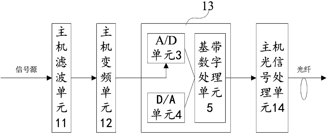
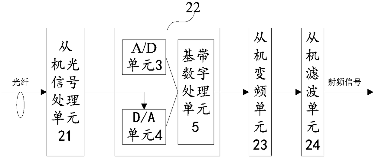
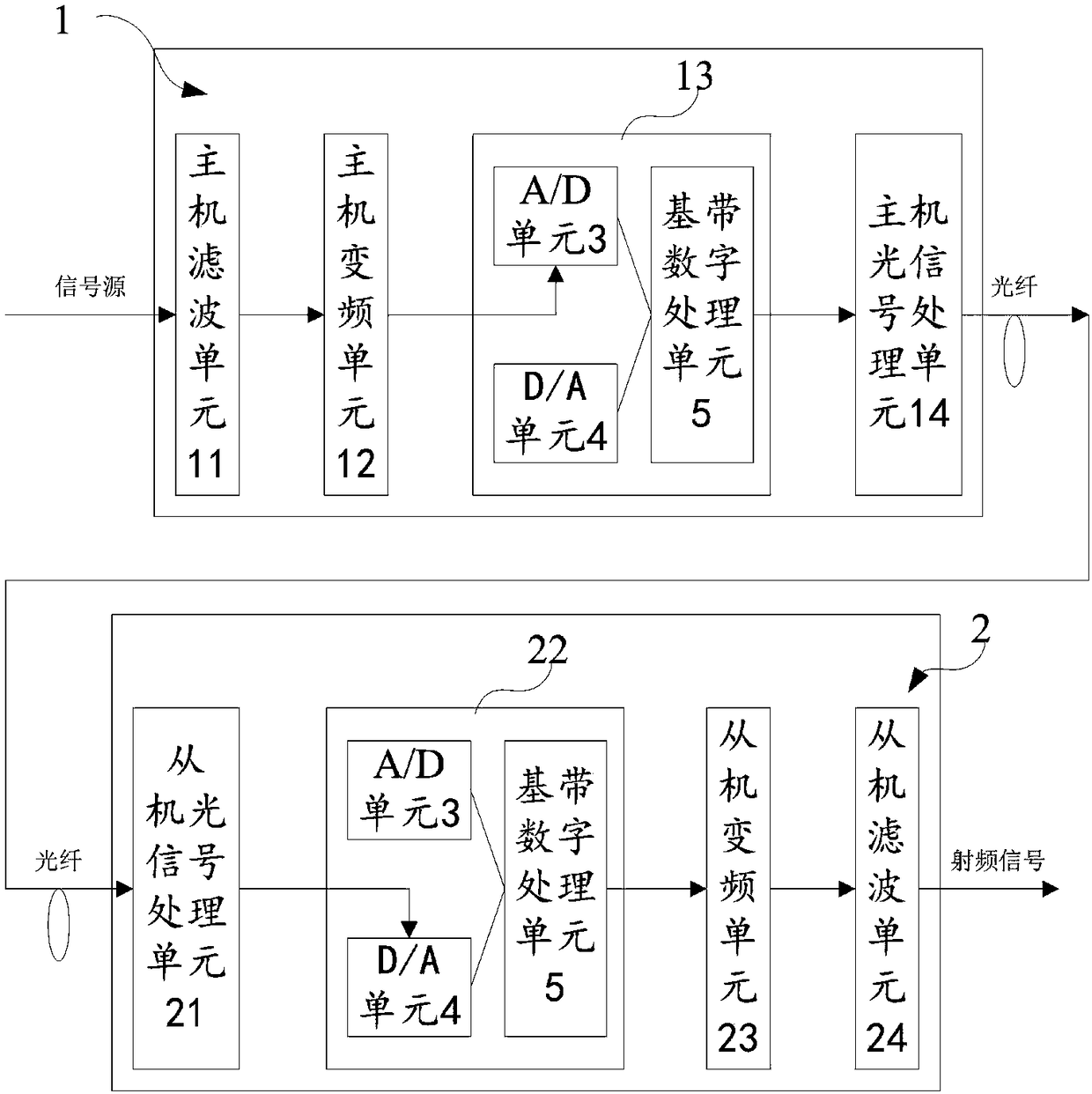
[0021] The synchronization principle of the radar signal synchronization system of the present invention is as follows: First, it is possible to perform site distribution by adjusting the fiber lengths of sites at different distances, which is beneficial to improve the characteristics of traditional single-frequency sites with limited distance and high site density; The automatic delay adjustment function of this system can effectively ensure the delay synchronization of multiple signal transmitting devices; in addition, with this optical fiber transmission system, only one source synchronization device needs to be configured in the radar computer room, and the traditional transmission system does not need to The configuration of source synchronization ...


PUM


Abstract

The invention discloses a radar signal synchronization system comprising a host device and at least one slave device. After filtering a signal source, the host device performs down-conversion processing to obtain an intermediate-frequency signal; conversion is carried out to obtain a zero-frequency signal; after digitization processing, an optical signal processing unit of the host carries out conversion to obtain an optical signal; the optical signal is transmitted to the slave device through a fiber; and the slave device receives the optical signal, carries out the reverse operation, and then sends the processed signal to a transmitting system for external transmission. After processing by the host device and the slave device, delay synchronization of multiple devices is ensured effectively; the networking cost is saved; and a defect of restriction by the website distance is overcome by the fiber transmission.

Description

technical field [0001] The invention relates to the technical field of radar communication, in particular to a radar signal synchronization system. Background technique [0002] At present, the radar arrays used in military reconnaissance can generate radar waves through the radar matrix, actively search for targets, and have strong search capabilities. However, due to strict requirements on the distance between each radar site, the density between the radar arrays is required to be large enough , and need source synchronization equipment at the same time, so the network construction cost is very high. Contents of the invention [0003] The technical problem to be solved by the present invention is to provide a radar signal synchronization system that uses optical fiber signal transmission, which can improve the disadvantage of limited distance between network points, and effectively ensure the time delay synchronization of multiple devices, saving network construction cos...

Claims


Application Information

Patent Timeline
IPC IPC(8): H04J3/06
CPCH04J3/0638
Inventor 苑红晓龙戈农李卫校袁志巍
Owner 郑州微纳科技有限公司
Why Eureka
Try Eureka