
Rotating shaft installation structure and cabinet using the rotating shaft installation structure

A technology of installation structure and rotating shaft, which is applied in the direction of casing/cabinet/drawer parts, substation/distribution device casing, electrical equipment casing/cabinet/drawer, etc. higher question

Active Publication Date: 2021-08-17
XJ ELECTRIC +2
View PDF12 Cites 0 Cited by
  • Summary
  • Abstract
  • Description
  • Claims
  • Application Information

AI Technical Summary

Problems solved by technology

[0003] The purpose of the present invention is to provide a rotating shaft installation structure to solve the problem of complicated disassembly and assembly of the rotating shaft in the prior art that does not require high transmission accuracy; it also provides a cabinet using the rotating shaft installation structure

Method used


Image

  • Rotating shaft installation structure and cabinet using the rotating shaft installation structure
  • Rotating shaft installation structure and cabinet using the rotating shaft installation structure
  • Rotating shaft installation structure and cabinet using the rotating shaft installation structure

Examples


Embodiment Construction

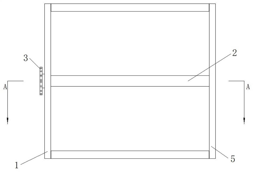
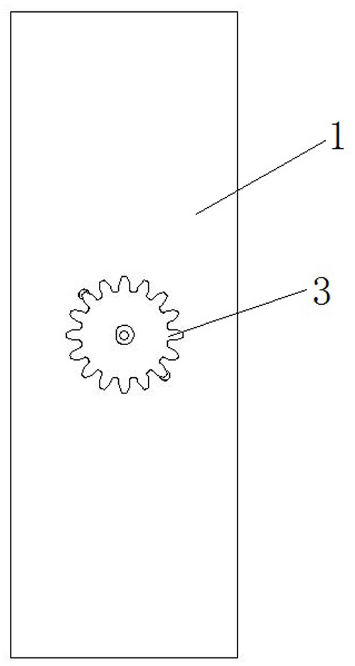
[0022] Embodiments of the present invention will be further described below in conjunction with the accompanying drawings.

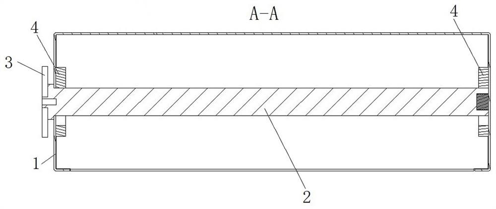
[0023] Specific embodiment one of the rotating shaft installation structure of the present invention, such as Figure 1 to Figure 6 As shown, the shaft installation structure includes a frame, and the frame includes a first bracket 1 and a second bracket 5 arranged at intervals on the left and right, and a shaft assembly 2 mounted on the two brackets. Wherein, the shaft assembly 2 passes through the first bracket 1 and the right end of the shaft assembly 2 presses against the second bracket 5 . The first bracket 1 is provided with a through hole for the rotating shaft assembly 2 to pass through.

[0024] The rotating shaft assembly 2 includes a rotating shaft 21. The rotating shaft 21 adopts a round steel rod treated by electroplating process. A blind hole is opened on the right end surface of the rotating shaft 21. A magnet 24 is installed in the blind...


PUM


Abstract

The invention relates to a rotating shaft installation structure and a cabinet using the rotating shaft installation structure, in order to solve the problem of complicated disassembly and assembly of the rotating shaft which does not require high transmission precision in the prior art. The rotating shaft installation structure includes a frame and a rotating shaft mounted on the frame. An axial stop structure is arranged between the frame and the rotating shaft, and a magnetic adsorption for axial positioning of the rotating shaft is realized by cooperating with the axial stop structure. structure. The magnetic adsorption structure can adsorb the rotating shaft on the frame, so as to ensure that the rotating shaft will not detach from the frame along the axial and radial directions of the rotating shaft, and at the same time meet the rotation requirements of the rotating shaft. For the rotating shaft that does not require high transmission accuracy and bears small radial and axial forces, when disassembling, it is only necessary to disconnect the disconnection and use the adsorption effect of the magnetic adsorption structure to disconnect the frame and the rotating shaft. Open and connect, the disassembly process is simple and convenient, which can reflect the advantages of its quick disassembly.

Description

technical field [0001] The invention relates to a rotating shaft installation structure and a cabinet using the rotating shaft installation structure. Background technique [0002] In the prior art, for the rotating shaft structure used in some mechanisms (such as switch cabinets), bearings, bushings, retaining rings, snap rings and other parts are generally used. The bearings and bushings can radially support the rotating shaft, and the retaining ring Components such as rings and snap rings can axially locate the shaft. In the prior art, when installing and disassembling the rotating shaft, it usually requires technicians with professional skills to install and disassemble the rotating shaft with the help of professional dismounting tools, and the installation and dismounting process is relatively complicated. However, for some rotating shafts that do not require high transmission accuracy, bear small axial force and radial force, and need to be disassembled and maintained...

Claims


Application Information

Patent Timeline
Patent Type & Authority Patents(China)
IPC IPC(8): H05K5/02H02B1/30
CPCH02B1/30H05K5/0217
Inventor 梁群胜袁敬海胡占伟刘鹏李哲杨鹏飞黄艳丽
Owner XJ ELECTRIC
Learn More