Improving temperature drift compensation by controlled over-compensation

An over-compensation, controller technology, applied in general control systems, program control, control/regulation systems, etc., to solve problems such as uncovered workspace, residual drift, and failure to consider temperature-related effects.

Inactive Publication Date: 2018-06-08
KUKA DEUT GMBH
View PDF7 Cites 0 Cited by
  • Summary
  • Abstract
  • Description
  • Claims
  • Application Information

AI Technical Summary

Problems solved by technology

But the risk of this approach is that there will be parts of the workspace that are not covered or temperat...

Method used


Image

  • Improving temperature drift compensation by controlled over-compensation
  • Improving temperature drift compensation by controlled over-compensation

Examples


Embodiment Construction

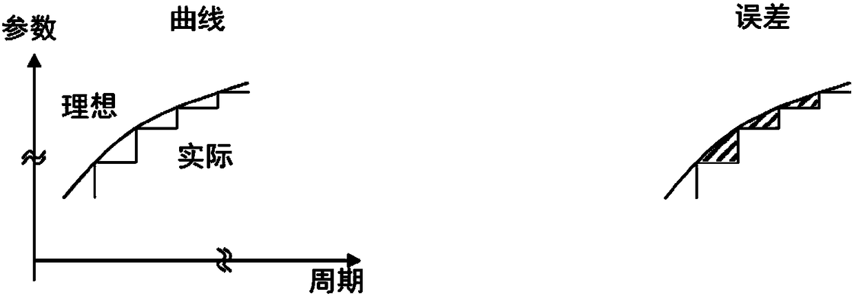
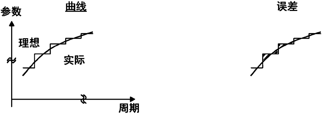
[0026] figure 1 and figure 2The parameter curves for a number of cycles are shown separately. Here, the parameters are manipulator parameters for controlling the manipulator. In the figures, the continuous lines represent the ideal curves of the parameters during these cycles. The parameters change due to temperature-dependent influences which occur, for example, during the warm-up phase of the manipulator. Especially at the beginning of the warm-up phase, the temperature rise can be very steep. Therefore, the manipulator parameters have a strong time dependence. In the best case, the currently used manipulator parameters agree with the ideal parameters at every point in time.

[0027] same as figure 1 As shown, the manipulator parameters are usually tuned to match ideal values ​​at the beginning of a cycle. For this purpose, for example, the usual temperature drift compensation can be used. The adjusted manipulator parameters remain constant during a duty cycle. Fro...


PUM


Abstract

The invention relates to a method for correcting a manipulator-parameter, wherein a manipulator is controlled at least by means of a manipulator-parameter. A change in the manipulator-parameter is determined over time and a residual error in the positional precision of the manipulator is corrected using the specific change in the manipulator-parameter over time.

Description

technical field [0001] The invention relates to a method for correcting manipulator parameters. Background technique [0002] Robots, especially industrial robots, are automatically controlled, freely programmable, multipurpose manipulators. They are designed for use in industrial environments and can be used in different areas of a production plant. For example, an industrial robot can be used to measure one or more measuring points of a component in a machining station or a measuring station, or to run a specific path program on a workpiece and thus process the workpiece or the component by means of, for example, a hemming tool. [0003] In order to be able to obtain a complete kinematic model of the robot, the industrial robot usually has to be calibrated before use. For this, various parameters of the robot mechanism must be determined in order to finally obtain a complete robot model. Furthermore, the robot must be oriented with respect to the component to be measure...

Claims


Application Information

Patent Timeline
IPC IPC(8): B25J9/16
CPCB25J9/1653B25J9/1692G05B2219/39192
Inventor R·米特曼S·卡得克M·海格R·米勒汤玛斯·普鲁克迈克尔·格勒尔
Owner KUKA DEUT GMBH
Why Eureka
Try Eureka