Magnet assembly for MRI comprising cylindrical rings of halbach type

一种核磁共振、海尔贝克的技术,应用在磁性物体、应用、磁体等方向,能够解决势能不均匀分布、降低内部磁场均匀性等问题

Active Publication Date: 2018-06-08
安东内洛索特奎
View PDF21 Cites 11 Cited by
  • Summary
  • Abstract
  • Description
  • Claims
  • Application Information

AI Technical Summary

Problems solved by technology

This creates a non-uniform distribution of potential energy which tends to reduce the homogeneity of the internal magnetic field

Method used


Image

  • Magnet assembly for MRI comprising cylindrical rings of halbach type
  • Magnet assembly for MRI comprising cylindrical rings of halbach type
  • Magnet assembly for MRI comprising cylindrical rings of halbach type

Examples


Embodiment Construction

[0031] magnet structure

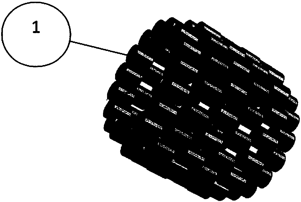
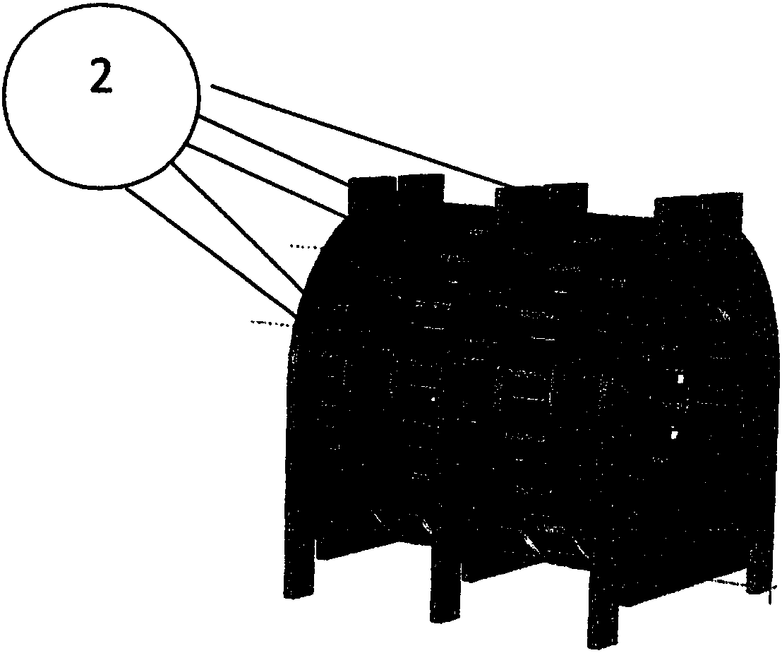
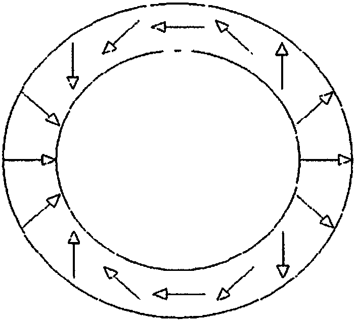
[0032] In the preferred embodiment shown in FIG. 1 , the magnet is formed by six Halbach rings divided into two subgroups, an inner ring 2 and two outer rings 1 . Each ring has 16 cylindrical blocks with hexagonal bases (Fig. 1). The magnetization direction of the block is perpendicular to the cylinder axis and points towards the center of one of the faces. In one run, the ring's magnetization completes a 720° rotation. Therefore, a magnet at angular position α will have a magnetization direction equal to 2*α.

[0033] Such as Figure 4 As shown, the inner rings have the same radius, while the spacing between the end rings is smaller in order to partially compensate for the effect of the finite length of the magnets. The bracket supporting the magnet is aluminum. The rotation of the magnetization on each ring confines the magnetic field within the magnet and requires neither an iron structure nor as a yoke or in the form of poles. This can obtai...


PUM


Abstract

The present invention identifies the construction methods and the techniques that allow to obtain a magnetic field of the field homogeneity required for the use in magnetic resonance imaging (MRI), inthe order of 20 parts per million (ppm) in the area of interest (such techniques in the following will be indicated with the word "shimming"). The peculiarity of the described constructive method isto obtain a homogeneous field region, usable for the MRI analysis, of linear dimensions equal to about 40% of the linear dimensions of the magnet. The shimming technique involves the use of conditioned magnetic material and allows to control accurately the magnetization of the corrective elements while using a material that inherently has a large spread in the magnetization value. The result is alow weight and small magnet suitable for MRI for dedicated clinical applications such as the analysis of the peripheral joint, the analysis of the ocular region, veterinary applications.

Description

technical field [0001] The invention relates to the technical field of a nuclear magnetic resonance imaging system and an imaging method. In particular, it relates to systems and methods for dedicated Magnetic Resonance Imaging (MRI) scanners. A dedicated MRI scanner is a device that can perform MRI analysis on designated parts of the human body. The magnets used in these applications are smaller than those commonly used in clinical diagnostics ("whole body" systems) and have smaller regions of uniformity. The typical Field of View (FOV) of a male clinical system is a sphere with a diameter of 40 / 50 cm, while the field of view of a dedicated peripheral joint system (hand, foot, knee) is a sphere with a diameter of approximately 16 cm. Typically, dedicated systems operate at magnetic field values ​​on the order of about 0.15T-0.3T and are defined as "low field systems". Background technique [0002] The magnet is the most critical component in an MRI scanner and must have ...

Claims


Application Information

Patent Timeline
Patent Type & Authority Applications(China)
IPC IPC(8): G01R33/383G01R33/3873
CPCG01R33/383G01R33/3873A61B5/055H01F7/0278
Inventor 安东内洛·索特奎
Owner 安东内洛索特奎
Why Eureka
Try Eureka