Improved injection dispensing valve

A spray point and improved technology, applied in the field of glue dispensing valve, can solve problems such as affecting working performance and unreasonable design of glue dispensing valve, etc., to achieve the effect of improving service life, conducive to glue discharge and fast exhausting

Pending Publication Date: 2018-06-12
苏州市睿成达电子有限公司
View PDF7 Cites 3 Cited by
  • Summary
  • Abstract
  • Description
  • Claims
  • Application Information

AI Technical Summary

Problems solved by technology

However, the design of the existing dispensing valve is not very reasonable, which affects the working performance to a certain extent

Method used


Image

  • Improved injection dispensing valve
  • Improved injection dispensing valve
  • Improved injection dispensing valve

Examples


Embodiment Construction

[0019] The following will clearly and completely describe the technical solutions in the embodiments of the present invention with reference to the accompanying drawings in the embodiments of the present invention. Obviously, the described embodiments are only some, not all, embodiments of the present invention. Based on the embodiments of the present invention, all other embodiments obtained by persons of ordinary skill in the art without making creative efforts belong to the protection scope of the present invention.

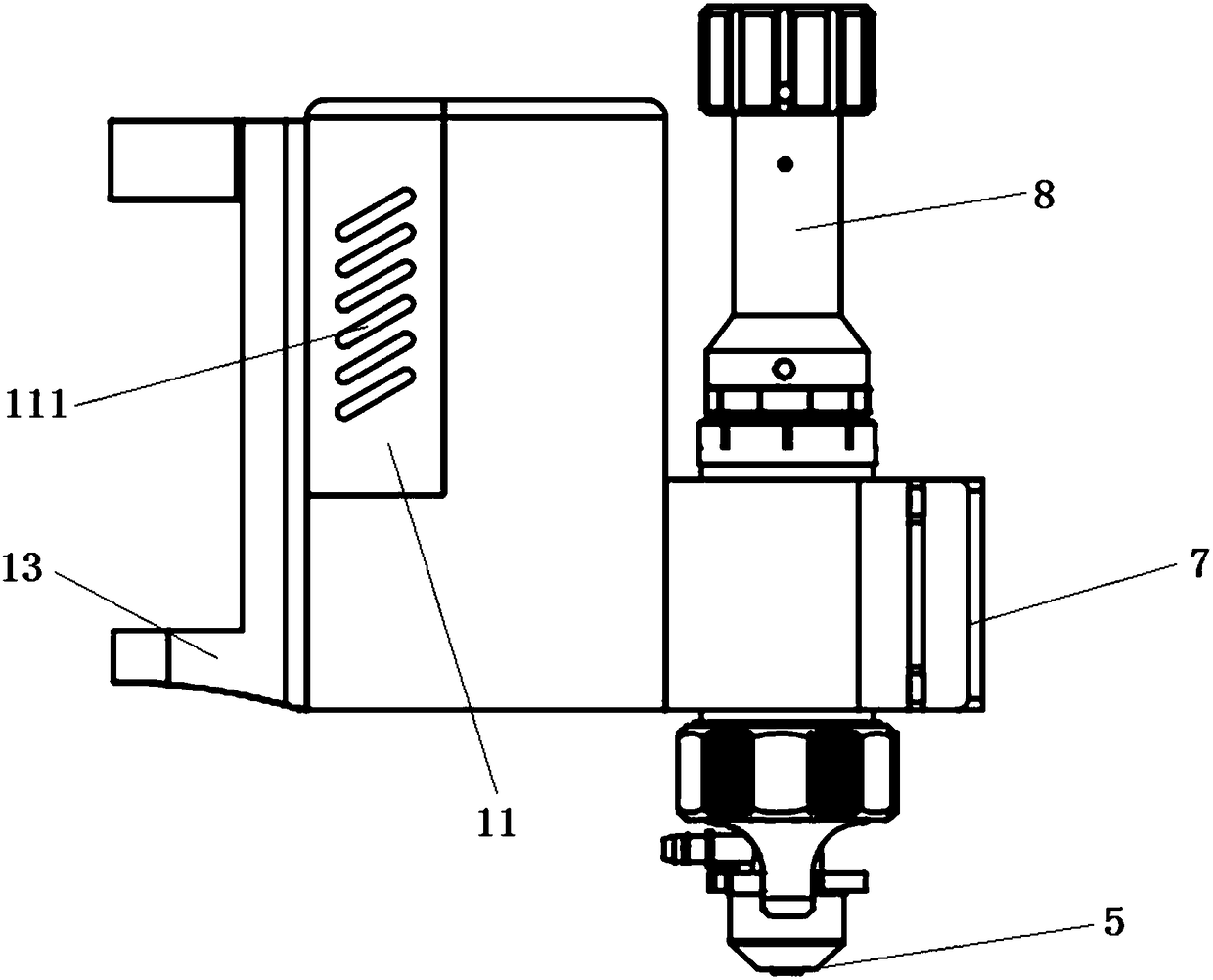
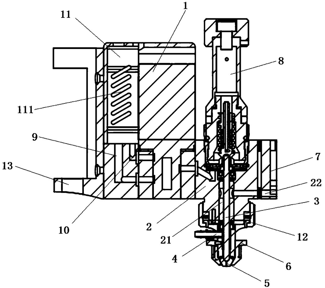
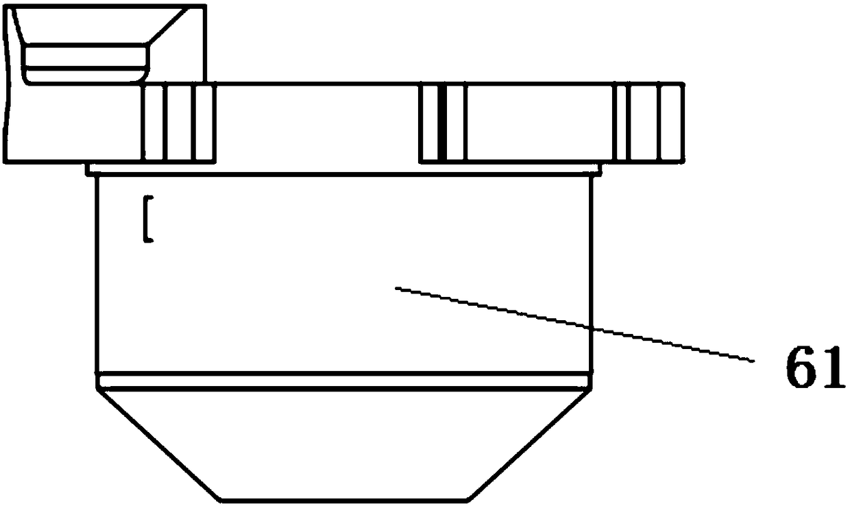
[0020] Such as Figure 1 to Figure 4 As shown, it is an improved jet dispensing valve according to the present invention, including: solenoid valve 1, valve body 2, striker 3, glue bin 4, nozzle 5, nozzle heater 6, valve base 7, stroke mechanism 8, Solenoid valve intake hole 9, solenoid valve exhaust hole 10, wire box 11, wherein said valve body 2 is fixedly arranged on said valve base 7, said valve body 2 upper end is provided with stroke mechanism 8, and the...


PUM


Abstract

The invention discloses an improved injection dispensing valve. The improved injection dispensing valve comprises an electromagnetic valve, a valve body, a firing pin, a glue bin, a sprayer, a sprayerheater, a valve base, a stroke mechanism, an electromagnetic valve gas inflow hole, an electromagnetic valve exhausting hole and a wire box, wherein the valve body is fixedly arranged on the valve base; the stroke mechanism is arranged at the upper end of the valve body; the lower end of the valve body is connected with the glue bin and the sprayer; the sprayer is sleeved with the sprayer heater;a cylindrical guiding column is arranged in the valve body, and is fixed to the valve base through a transversely arranged screw; a carrying mechanism is arranged on the side, away from the valve body, of the valve base; the firing pin is arranged in the cylindrical guiding column; the lower end of the firing pin is in abutting contact with the inner side of the sprayer; the electromagnetic valveis transversely and fixedly arranged on one side of the valve body, and is provided with the electromagnetic valve gas inflow hole and the electromagnetic valve exhausting hole; the side, away from the valve body, of the electromagnetic valve is connected with the wire box which is provided with cooling holes, and cooling of the electromagnetic valve is facilitated.

Description

technical field [0001] The invention relates to the technical field of dispensing valves, in particular to an improved jet dispensing valve. Background technique [0002] In the packaging process of industrial products, the use of injection valves has become more and more extensive. The injection valve sprays a small amount of high-viscosity fluid (flux, conductive glue, epoxy resin and adhesive, etc.) to the appropriate position of the workpiece (chip, electronic component, etc.) to achieve mechanical or electrical connections between components. However, the design of the existing dispensing valve is not very reasonable, which affects the working performance to a certain extent. [0003] Therefore, the inventors of the present invention urgently need to conceive a new technology to improve the problem. Contents of the invention [0004] In order to solve the above technical problems, the present invention provides an improved jet dispensing valve. [0005] Technical s...

Claims


Application Information

Patent Timeline
Patent Type & Authority Applications(China)
IPC IPC(8): B05C5/02B05C5/00
CPCB05C5/001B05C5/0225
Inventor 吴兴理杨乐
Owner 苏州市睿成达电子有限公司
Why Eureka
Try Eureka