Multifunctional automatic hairbrush

A multi-functional, automatic technology, applied in brushes, brushes, household appliances, etc., to achieve the effect of improving automation, eliminating waste, and saving time for ingredients

Inactive Publication Date: 2018-11-06
重庆博巨玻璃钢有限公司
View PDF7 Cites 3 Cited by
  • Summary
  • Abstract
  • Description
  • Claims
  • Application Information

AI Technical Summary

Problems solved by technology

In this way, after the bristles are arranged on the sliders that can slide back and forth toward each other, when the brush is used for brushing, the brush will perform telescopic movement toward the mold parting surface, so that the brush and the mold parting surface are in constant contact. In this way, the operator can avoid the problem of arm soreness caused by repeated shaking of the arm

Method used


Image

  • Multifunctional automatic hairbrush
  • Multifunctional automatic hairbrush
  • Multifunctional automatic hairbrush

Examples


Embodiment 1

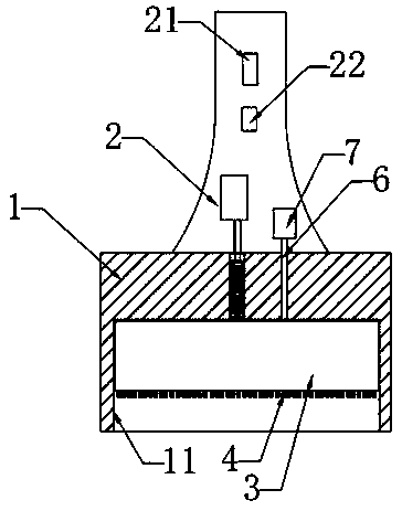
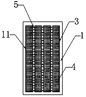
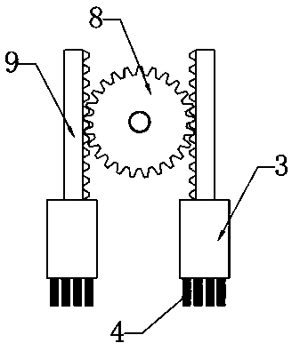
[0023] Such as figure 1 , image 3 As shown, the transmission mechanism includes a servo motor, a gear 8 fixedly connected to the output shaft of the servo motor, and a rack 9 meshing with the gear 8 is respectively arranged on the left and right sides of the gear 8, and the rack 9 is located at the brush Inside the body 1, the racks 9 are arranged vertically and parallel to the central axis in the thickness direction of the brush body 1. Each rack 9 corresponds to a slider 3, and the slider 3 is fixedly installed on the lower end of the rack 9. When the servo motor starts, it drives the gear 8 fixedly connected with it to rotate, and after the gear 8 rotates, it drives the racks 9 meshing with it on both sides to slide upwards and downwards respectively, thereby realizing the opposite movement of two adjacent sliders 3 . At the same time, when the rack 9 slides a certain distance, the servo motor controls its output shaft to reverse, so that the gear 8 will reverse according...

Embodiment 2

[0027] Above-mentioned transmission mechanism can adopt existing crank-link mechanism to replace. Specifically, the transmission mechanism includes a motor, a crank and a connecting rod. One end of the connecting rod is connected to the crank, and the other end is fixedly connected to the slider 3. The crank is connected to the motor, and the motor drives the crank to rotate. After the crank rotates, Drive the connecting rod to move, thereby driving the slider 3 to reciprocate up and down.

[0028] In addition, in order to facilitate the control of the operation of the slider 3 and the nozzle assembly, the brush handle 2 is provided with a vibration switch 21 for controlling the opening and closing of the servo motor that drives the slider 3 to slide, and a vibration switch 21 for controlling the opening and closing of the motor for the nozzle assembly to absorb paint. Injection switch 22.

Embodiment 3

[0030] Specifically, each slider 3 corresponds to a transmission mechanism, and the transmission mechanism includes an air compressor, and a plurality of airflow passages connected with the exhaust port of the air compressor are arranged in the brush body, and each airflow passage corresponds to a slider 3. A return spring corresponding to the airflow channel is fixedly installed on each slider 3 . When in use, the high-pressure gas generated by the air compressor makes the spring-mounted slider 3 move under pressure, and when it reaches a certain position, the gas pressure is released, and the slider 3 rebounds under the action of the spring to realize the up and down movement.


PUM


Abstract

The invention discloses a multifunctional automatic hairbrush. The hairbrush comprises a brush body and a brush handle; the hairbrush is characterized in that at least two slide blocks which oppositely and retractably slide in the length direction of the brush body are arranged in the brush body, and multiple groups of bristles are uniformly distributed on the outer end face of each slide block; at least one nozzle assembly is arranged on the portion, between every two slide blocks, of the brush body or on each slide block, and each nozzle assembly comprises at least two nozzles, and is communicated with a solvent bucket through a paint delivery pipeline. By means of the multifunctional automatic hairbrush, the bristles are arranged on the slide blocks which can oppositely and retractablyslide, the labor intensity of operating personnel is reduced, and the quality of dipping brushing is improved; meanwhile, in the spraying process, the arranged nozzle assemblies directly spray raw coating materials onto objects, dripping and leakage occurring when the hairbrush is transferred while dipped with paint are prevented, the waste of the paint is reduced, and dynamic matching of the multi-component hybrid reaction paint can also be achieved.

Description

technical field [0001] The invention relates to a tool for hand lay-up of glass fiber reinforced plastics, in particular to a multifunctional automatic brush. Background technique [0002] The forming process of FRP products is mainly divided into hand lay-up forming process, pultrusion forming process, winding forming process and compression molding process. Among them, the hand lay-up molding process, also known as contact molding, is the earliest and most widely used molding method in the production of resin-based composite materials. The hand lay-up molding process is based on the resin mixture with curing agent as the matrix, glass fiber and its fabric as the reinforcing material, and is manually placed on the mold coated with the release agent to bond the two together. A process for manufacturing FRP products. The process of the hand lay-up molding process is: first apply the release agent on the cleaned or surface-treated mold molding surface, and after it is fully ...

Claims


Application Information

Patent Timeline
IPC IPC(8): A46B11/02A46B13/04A46B13/02
CPCA46B11/0024A46B11/0072A46B13/023A46B13/04A46B2200/202
Inventor 黄林
Owner 重庆博巨玻璃钢有限公司
Why Eureka
Try Eureka