
Clutch petal assembly

A clutch pedal and assembly technology, which is applied to control devices, transportation and packaging, vehicle components, etc., can solve the problems of metal pin shaft sleeves coming out, abnormal noise, etc., and achieve the effect of avoiding shifting shock and returning to the original position.

Pending Publication Date: 2018-06-12
BRILLIANCE AUTO
View PDF0 Cites 0 Cited by
  • Summary
  • Abstract
  • Description
  • Claims
  • Application Information

AI Technical Summary

Problems solved by technology

However, the metal pin shaft sleeve may come out of the pedal arm hole during mass use and cause abnormal noise

Method used


Image

  • Clutch petal assembly
  • Clutch petal assembly
  • Clutch petal assembly

Examples

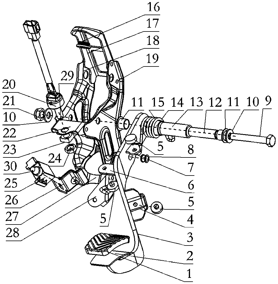
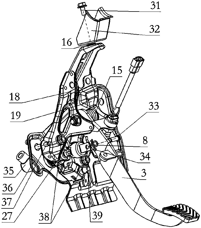

Embodiment Construction

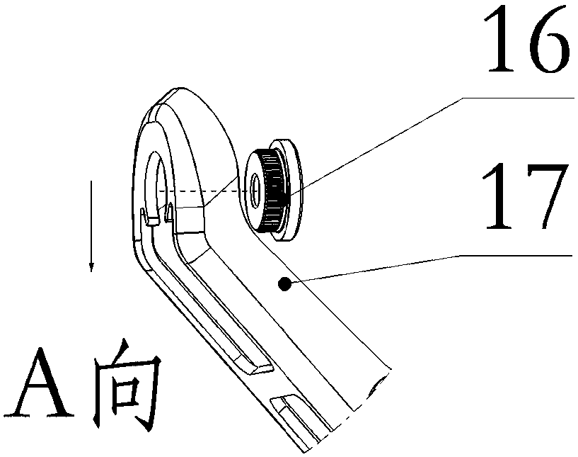
[0025] To make the above-mentioned purposes, features and advantages of the present invention more obvious and understandable, below in conjunction with the attached Figure 1 ~ Figure 3 The present invention will be further described in detail with specific embodiments.

[0026] A clutch pedal assembly, including a clutch bracket body composed of upper bracket 17, left bracket 18, right bracket 19, and lower bracket 27 welded together, and a pedal cover 1 and a pedal pad body 2 connected to the clutch bracket body. Pedal arm 3, axle sleeve 13 first passes through the axle sleeve mounting hole of pedal arm 3, then is fixed between the left support 18 and the right support 19 with the mounting hole on the right support 19 and the mounting hole on the left support 18 successively, and in The inner ring of the shaft sleeve 13 is connected with the shaft tube 12, and one end of the shaft tube 12 is provided with a self-lubricating bearing 11, the inner ring of the shaft sleeve 13 ...


PUM


Abstract

The invention relates to a vehicle clutch control system or part, in particular to a clutch petal assembly. A clutch petal upper switch, a clutch petal lower switch and a clutch petal self-limiting mechanism are arranged on a clutch support body, a crushing nut is connected to an upper support in a riveted mode, and a return spring is further arranged on a shaft sleeve between the upper support and a lower support. When a clutch is stepped, the upper switch is connected, an engine control unit receives a signal of the upper switch, the ignition advance angle is decreased, the oil spraying amount is decreased, power storage is carried out, the gear shifting impact is avoided, the service life of a clutch system is prolonged, and oil consumption is reduced. When a clutch pedal is stepped tothe bottom, the clutch system is disconnected, the clutch petal lower switch is connected, a clutch system disconnection signal is provided for a keyless entry system, and safe starting of an automobile is ensured. Through the crushing nut, the situations that when the automobile is collided, a clutch main cylinder moves backwards and is disengaged from the upper support, the clutch petal rotatesaround the mounting point of the crushing nut and an instrument cross beam support, and consequently a left shank is hurt can be prevented.

Description

technical field [0001] The invention relates to a vehicle clutch control system or its components, in particular to a clutch pedal assembly. Background technique [0002] With the rapid development of the automobile industry, customers have higher and higher requirements for automobiles. At the same time, customers have higher and higher requirements for driving comfort and power economy. The clutch pedal assembly is used as a control mechanism to control the engagement and separation of the clutch system, so as to ensure the smooth start of the car, realize smooth gear shifting, and prevent the drive train from overloading. [0003] The existing clutch pedal adopts a bolt structure to realize the upper limit function. When the clutch pedal is stepped on, the engine cannot judge whether the clutch system is disconnected. At this time, the power of the clutch system is suddenly disconnected, the load disappears, and the engine speed increases, which will cause engine failure...

Claims


Application Information

Patent Timeline
IPC IPC(8): B60K23/02
CPCB60K23/02
Inventor 王健梁杰田明
Owner BRILLIANCE AUTO
Learn More