A series-parallel hybrid transmission

A technology of hybrid power and transmission, applied in the field of series-parallel hybrid transmission, which can solve the problems of low driving efficiency, high power motor torque requirements, high cost, etc., and achieve the effects of improving power performance, avoiding shifting impact, and high driving efficiency

Active Publication Date: 2022-03-04
CHINA THREE GORGES UNIV
View PDF0 Cites 0 Cited by
  • Summary
  • Abstract
  • Description
  • Claims
  • Application Information

AI Technical Summary

Problems solved by technology

[0003] Parallel hybrid transmissions can be divided into different configurations such as P0, P1, P2, P2.5, P3, and P4 according to the position of the power motor or the coupling element. Among them, the P2.5 configuration is specially designed for "dual clutch transmission (DCT) + motor" structure, the overall cost is relatively high; the P0 configuration replaces the original conventional generator with a power motor, and the P1 configuration places the motor between the internal combustion engine and the main clutch. The disadvantage of these two configurations is that Low kinetic energy recovery efficiency, no independent electric drive capability or low drive efficiency; the P2 configuration places the power motor between the main clutch and the transmission, mostly with an automatic transmission (AT) with a hydraulic torque converter, or with a transmission belt When used in conjunction with CVT, there are still problems of high cost and low efficiency; when matched with mechanical automatic transmission (AMT) and dual clutch transmission (DCT) (P2.5 configuration), there will be a problem of power interruption for shifting; The P3 configuration puts the motor at the end of the transmission, and the P4 configuration puts the motor on another drive axle. In the case of using a single motor, the P3 and P4 configurations will not be able to realize the parking charging function, and the torque requirements of the power motor are relatively high.

Method used


Image

  • A series-parallel hybrid transmission
  • A series-parallel hybrid transmission
  • A series-parallel hybrid transmission

Examples


Embodiment 1

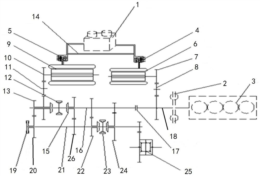
[0030] Such as figure 1 Among them, a series-parallel hybrid transmission includes a transmission device, a wire harness, a shock absorber 2, an internal combustion engine 3, and a controller. The transmission device includes a battery 1 and a battery management system, and the battery 1 and the first inverter 4 It is connected with the second inverter 5, the first inverter 4 is connected with the first motor 6, the output end of the first motor 6 is provided with a first gear 7, and the first gear 7 is connected with the second input through the first idler gear 8. The shaft 18 is connected, the second inverter 5 is connected with the second motor 9, the output end of the second motor 9 is provided with a second gear 10, the second gear 10 is connected with the first input shaft 16 through the second idler gear 11, and the second gear 10 is connected with the first input shaft 16 through the second idler gear 11. An input shaft 16 is provided with a first synchronizer 12 and ...

Embodiment 2

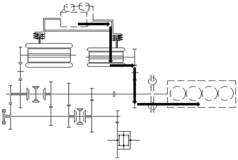
[0038] Such as figure 2 In the transmission path of the cold start internal combustion engine: it is detected that the SOC is less than the specified value, the main clutch 17 and the auxiliary clutch 19 are disconnected, the first synchronizer 12 is in the neutral position, the battery 1 → the first inverter 4 → the first motor 6 → the first Gear 7→first idler gear 8→second input shaft 18→shock absorber 2→internal combustion engine 3.

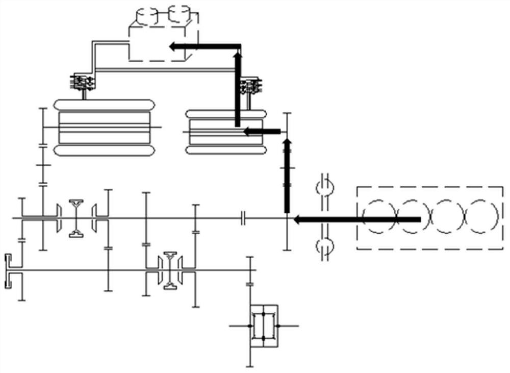
[0039] Such as image 3 , parking charging path: main clutch 17 and auxiliary clutch 19 are disconnected, first synchronizer 12 is in neutral position, internal combustion engine 3→shock absorber 2→second input shaft 18→first idler gear 8→first gear 7→ The first motor 6→the first inverter 4→the battery 1 .

[0040] Such as Figure 4 In the middle, the pure electric first-gear drive power transmission path: the main clutch 17 and the auxiliary clutch 19 are disconnected, the first synchronizer 12 turns to the right position, the second sync...

Embodiment 3

[0059] Such as Figure 1-15 In the description of the working conditions of the dual-motor embodiment, in the table, ON: the internal combustion engine 3 is running; OFF: the internal combustion engine 3 is off; O: the synchronizer is neutral or the clutch is disconnected or the motor is idling; X: the clutch is engaged; Shift to the right; ←: Synchronizer shifts to the left; M: Motor output power; G: Motor accepts power and generates power.

[0060]


PUM


Abstract

A series-parallel hybrid transmission, including a transmission device, a wiring harness, a shock absorber, an internal combustion engine, and a controller. The transmission device includes a battery and a battery management system, and the battery is connected to the first inverter and the second inverter , the first inverter is connected to the first motor, the output end of the first motor is provided with a first gear, the first gear is connected to the second input shaft through the first idler gear, the second inverter is connected to the second motor, The output end of the second motor is provided with a second gear, and the second gear is connected with the first input shaft through the second idler gear. The first input shaft is provided with a first synchronizer and a fourth-speed main gear. The clutch is connected to the second input shaft, and the second input shaft is connected to the internal combustion engine through the shock absorber. By adopting the above-mentioned structure, the fuel consumption can be reduced as much as possible, the impact of gear shifting can be reduced, and the power performance can be improved.

Description

technical field [0001] The invention relates to the field of automobile manufacturing, in particular to a series-parallel hybrid transmission. Background technique [0002] Hybrid technology can better reduce fuel consumption and emissions, and it also continues the traditional vehicle technology well. The technical threshold is relatively low, and the motor control technology is becoming more and more mature. There are many implementation forms of hybrid electric vehicles, and the most common ones on the market are parallel hybrid systems and hybrid hybrid systems. The parallel hybrid system is based on the conventional transmission, adding one or two power motors to transmit power to the vehicle axle in parallel, usually equipped with a charging device to form a plug-in hybrid transmission. [0003] Parallel hybrid transmissions can be divided into different configurations such as P0, P1, P2, P2.5, P3, and P4 according to the position of the power motor or the coupling el...

Claims


Application Information

Patent Timeline
Patent Type & Authority Patents(China)
IPC IPC(8): B60K6/42B60K6/54B60K6/36B60K6/38
CPCB60K6/42B60K6/54B60K6/36B60K6/38
Inventor 李响曹祥斌李书璇
Owner CHINA THREE GORGES UNIV
Why Eureka
Try Eureka