Self-positioning joint between fabricated concrete filled steel tubular columns and construction method thereof

A steel tube concrete column and assembly technology, applied in the direction of columns, pier columns, pillars, etc., can solve the problems of poor aesthetics, long construction period, difficult installation and positioning of flange bolt holes, etc., to reduce the value of tensile stress, The effect of high construction quality

Active Publication Date: 2018-06-12
FUZHOU UNIV
View PDF7 Cites 15 Cited by
  • Summary
  • Abstract
  • Description
  • Claims
  • Application Information

AI Technical Summary

Problems solved by technology

However, in actual engineering, the circular steel pipe concrete columns are mostly cast-in-place components, which have the following disadvantages: 1) Due to the limitation of on-site construction conditions and curing conditions, the quality of concrete pouring is not easy to guarantee; 2) Since the concrete curing generally takes seven days, the construction long cycle
On the other hand, the existing codes only suggest prefabricated steel pipe concrete columns connected by flanges, which still have the following problems: 1) The connection part protrudes outside the steel pipe wall, so the aesthetics is poor, and the Suitable for use in residential and large public buildings; 2) The installation and positioning of the upper and lower columns and their flange bolt holes is difficult

Method used


Image

  • Self-positioning joint between fabricated concrete filled steel tubular columns and construction method thereof
  • Self-positioning joint between fabricated concrete filled steel tubular columns and construction method thereof
  • Self-positioning joint between fabricated concrete filled steel tubular columns and construction method thereof

Examples


Embodiment Construction

[0029] In order to make the above-mentioned features and advantages of the present invention more comprehensible, the following specific embodiments are described in detail with reference to the accompanying drawings.

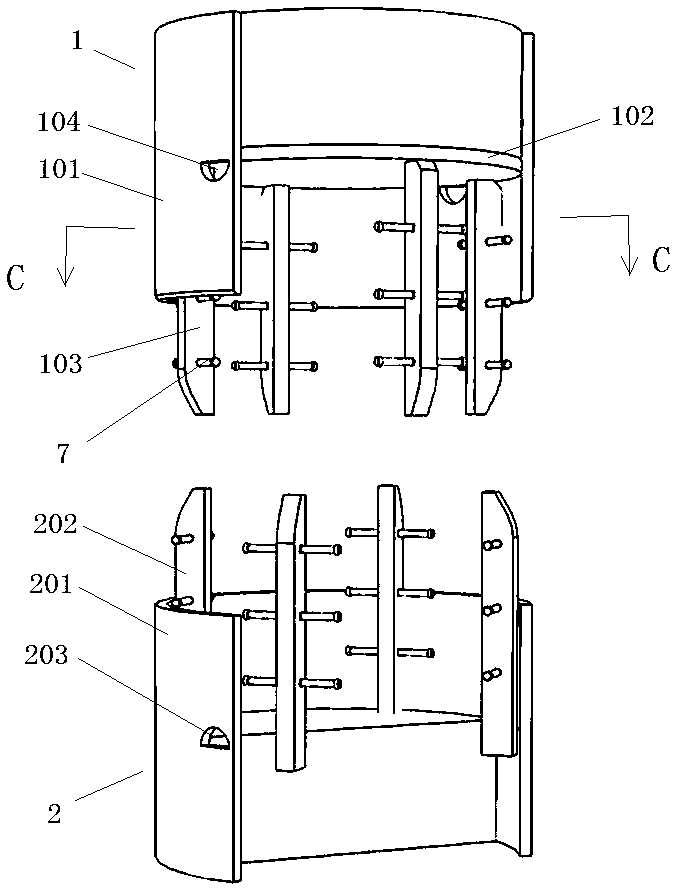
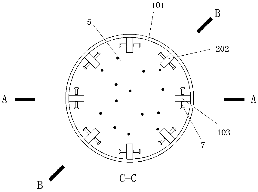
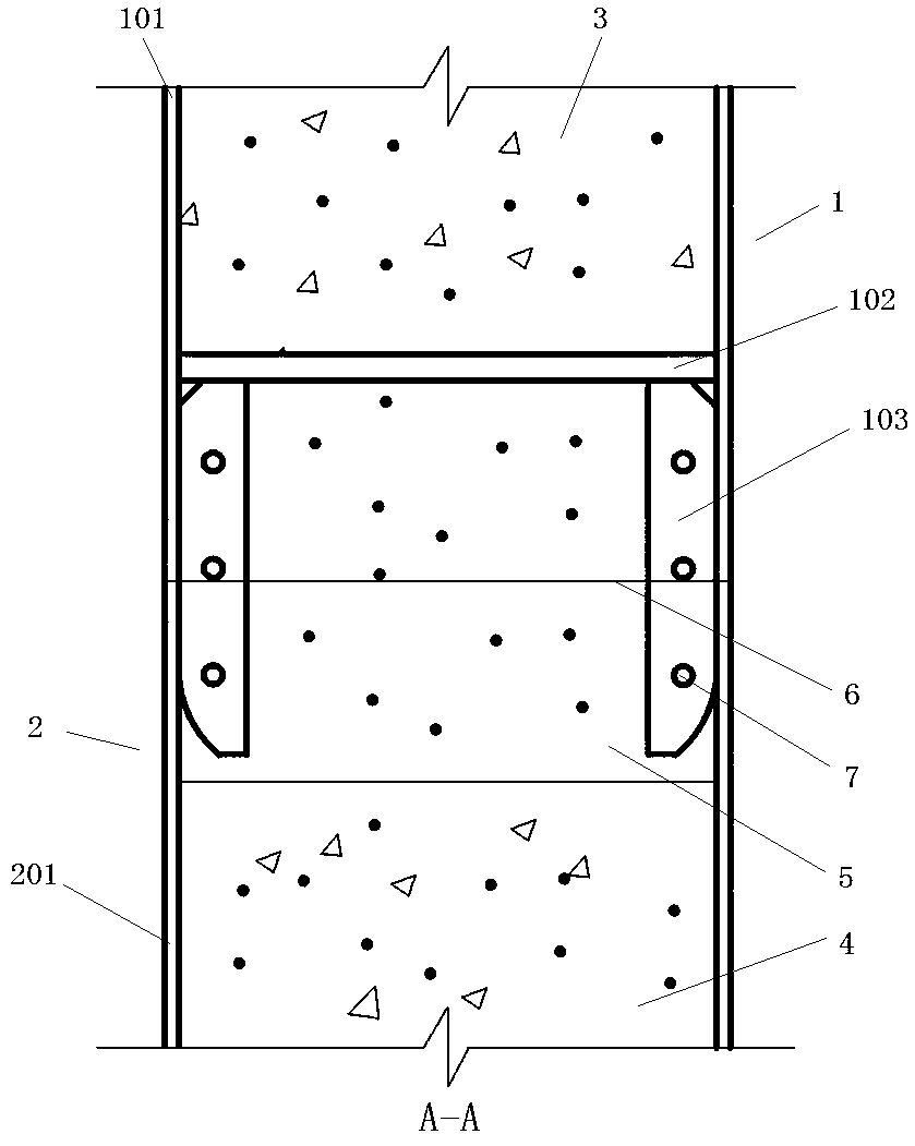
[0030] Such as Figure 1~4 As shown, a self-positioning assembled concrete-filled steel tube inter-column node includes a prefabricated upper column 1 and a prefabricated lower column 2, the bottom of the prefabricated upper column 1 and the top of the prefabricated lower column 2 are welded together, and the prefabricated upper column The upper part of 1 is poured with upper column concrete 3, the lower part of the prefabricated lower column 2 is poured with lower column concrete 4, and the lower part of the prefabricated upper column 1 and the upper part of the prefabricated lower column 2 are poured with cement-based grouting material 5.

[0031] In the embodiment of the present invention, the prefabricated upper column 1 includes an upper column steel pipe ...


PUM


Abstract

The invention relates to a self-positioning joint between fabricated concrete filled steel tubular columns and further relates to a construction method of the self-positioning joint between the concrete filled steel tubular columns. The self-positioning joint comprises the upper prefabricated column and the lower prefabricated column. The bottom of the upper prefabricated column and the top of thelower prefabricated column are welded together; upper column concrete is poured in the upper portion of the upper prefabricated column, and lower column concrete is poured in the lower portion of thelower prefabricated column; and cement-based grouting materials are poured in both of the lower portion of the upper prefabricated column and the upper portion of the lower prefabricated column. Theself-positioning joint is simple in structural design, safe, reliable, efficient, convenient, rapid and easy to mount, position and construct.

Description

technical field [0001] The invention relates to a self-positioning assembled steel pipe concrete column inter-column node and a construction method thereof. Background technique [0002] Circular concrete-filled steel tube columns have the advantages of high bearing capacity, small cross-section, good seismic performance and convenient construction. This type of component has been widely used in high-rise and long-span building structures, which is in line with the national trend of vigorously developing green buildings and prefabricated structures. However, in actual engineering, the circular steel pipe concrete columns are mostly cast-in-place components, which have the following disadvantages: 1) Due to the limitation of on-site construction conditions and curing conditions, the quality of concrete pouring is not easy to guarantee; 2) Since the concrete curing generally takes seven days, the construction The cycle is long. On the other hand, the existing codes only sugge...

Claims


Application Information

Patent Timeline
Patent Type & Authority Applications(China)
IPC IPC(8): E04C3/34E04B1/58
CPCE04B1/585E04C3/34
Inventor 王志滨沈蔚
Owner FUZHOU UNIV
Why Eureka
Try Eureka