
Rapid dust falling device and method for tunnel construction

A dust suppression device and tunnel construction technology, applied in safety devices, dust prevention, earth-moving drilling and other directions, can solve the problems of inability to meet the requirements of tunnel construction environment, endanger the health of tunnel construction workers, and generate a large amount of toxic and harmful gases, etc. The effect of waiting time for dust reduction, shortening dust reduction time, and avoiding close contact with dust

Pending Publication Date: 2018-06-12
CHANGAN UNIV +1
View PDF0 Cites 9 Cited by
  • Summary
  • Abstract
  • Description
  • Claims
  • Application Information

AI Technical Summary

Problems solved by technology

[0002] At present, highways, railways and urban construction continue to flourish, and the number of tunnels is gradually increasing, and the quality requirements for tunnel construction are becoming more and more stringent. When the drill and blast method is used for tunnel excavation, a large amount of toxic and harmful gases will be easily produced in the area near the tunnel face after blasting or during support operations, which will seriously endanger the health of tunnel construction workers.
At present, most of the existing tunnel construction dust reduction measures mainly adopt ventilation and water spraying as a supplementary measure, resulting in a long waiting time for dust reduction, and part of the dust still remains in the air, which cannot achieve fast dust reduction and cannot meet the environmental requirements of tunnel construction. The construction progress of the tunnel, and the status of the dust suppression device cannot be automatically adjusted according to the dust concentration in the tunnel, so that the dust suppression device is always on, resulting in waste of water resources and greatly increasing the cost of dust suppression

Method used


Image

  • Rapid dust falling device and method for tunnel construction
  • Rapid dust falling device and method for tunnel construction
  • Rapid dust falling device and method for tunnel construction

Examples


Embodiment

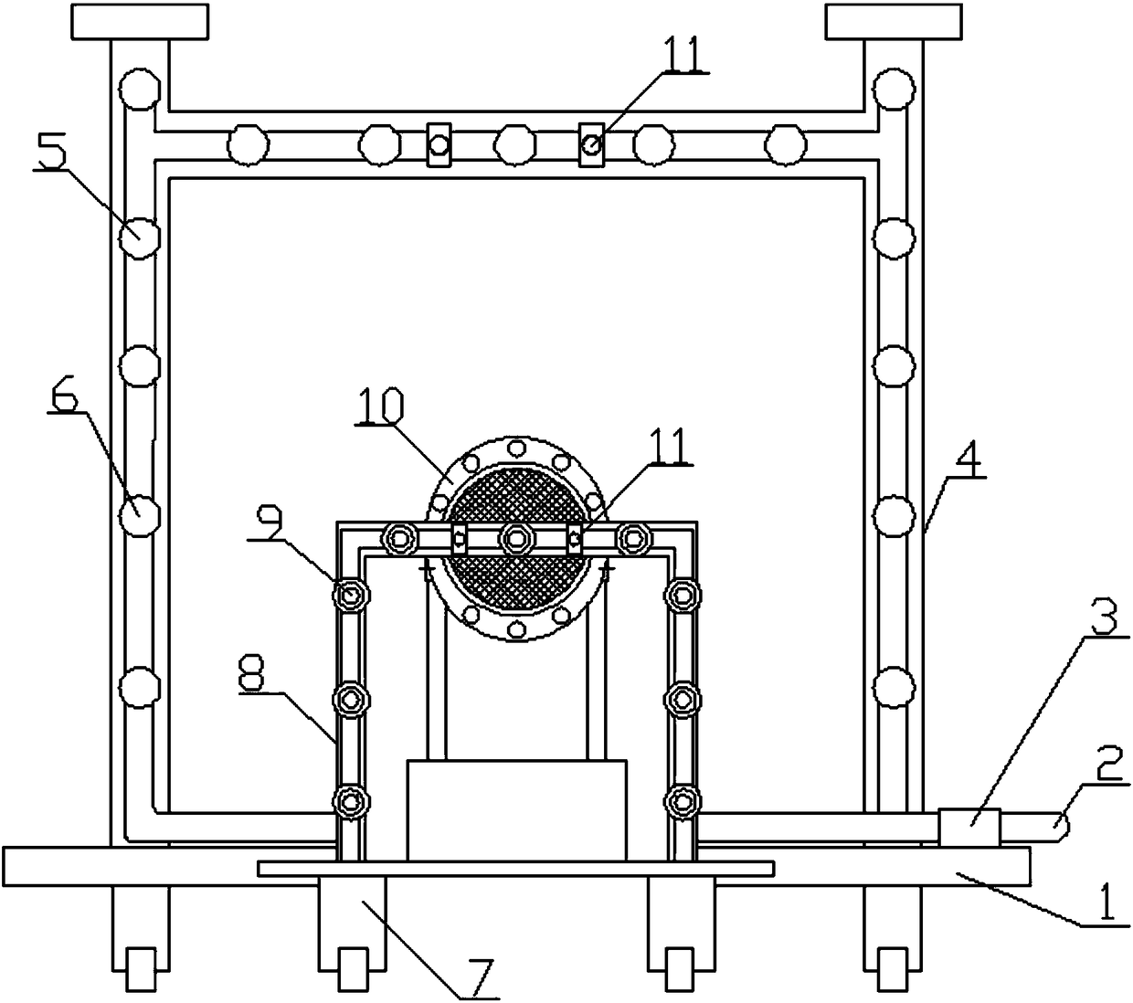
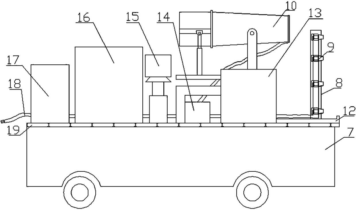
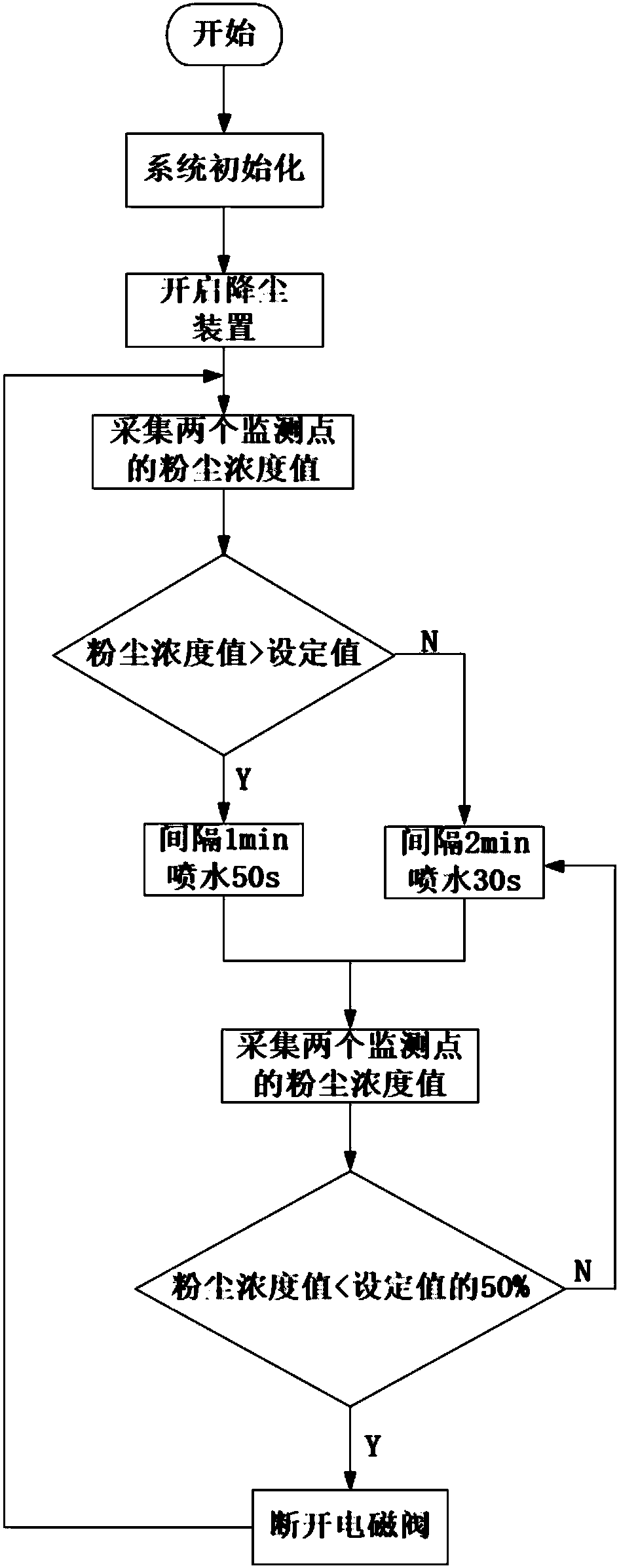
[0043] In the dust reduction process of this embodiment, the GCG1000 type dust concentration sensor feeds back the dust detection concentration synchronously to the electric control device 13, and the electric control device 13 compares the detection concentration with the dust concentration set value (6mg / m3), when the detection concentration When it is greater than the set value, control the dust suppression device to spray water for 50s every 1min. When the detected concentration is greater than 50% of the set value, control the dust suppression device to spray water for 30s every 2min. When the detected concentration is less than 50% of the set value, The electric control device 13 controls the solenoid valve 14 to automatically close. According to the difference in dust concentration near the tunnel face, the electric control device 13 can automatically adjust the dust reduction time of the second dust reduction device 8 and the air-driven dust reduction device 10 according...


PUM


Abstract

The invention discloses a rapid dust falling device and method for tunnel construction. The rapid dust falling device comprises a first dust falling device and a booster pump which are installed on atunnel excavating trolley, and a second dust falling device, an air-conveying dust falling device, an electronic control device, a magnetic valve, a high pressure water pump and a water tank which areinstalled on a moving trolley; dust concentration sensors are separately installed on the moving trolley and the tunnel excavating trolley; the booster pump, the magnetic valve, the high pressure water pump, a motor of the air-conveying dust falling device and the dust concentration sensors are all connected with the electronic control device; inlets of the booster pump and the high pressure water pump communicate with the water tank, the magnetic valve is arranged at the outlet of the high pressure water pump, and a second dust falling device and the air-conveying dust falling device are separately connected with the outlet of the magnetic valve; and the outlet of the booster pump is connected with the first dust falling device through a pipeline. According to the rapid dust falling device and method for the tunnel construction, two dust falling barriers are formed close to a tunnel face, and the water spray time of dust falling is automatically adjusted according to the difference of dust concentration, so that the dust falling efficiency is improved, water resources are saved, the waiting time for the dust falling is shortened, and the progress of the tunnel construction is accelerated.

Description

technical field [0001] The invention belongs to the field of rapid dust reduction in tunnel construction, in particular to a device and method for rapid dust reduction in tunnel construction. Background technique [0002] At present, highways, railways and urban construction continue to flourish, and the number of tunnels is gradually increasing, and the quality requirements for tunnel construction are becoming more and more stringent. When the drill and blast method is used for tunnel excavation, a large amount of toxic and harmful gases are likely to be generated in the vicinity of the tunnel face after blasting or during support operations, seriously endangering the health of tunnel construction workers. At present, most of the existing tunnel construction dust reduction measures mainly adopt ventilation and water spraying as a supplementary measure, resulting in a long waiting time for dust reduction, and part of the dust still remains in the air, which cannot achieve fa...

Claims


Application Information

Patent Timeline
IPC IPC(8): E21F5/04
CPCE21F5/04
Inventor 王海英王超翟鹏辉雷甲王馨平林枫赵晓晓
Owner CHANGAN UNIV
Learn More