Cable adapter

A docking device and optical cable technology, which is applied in the field of optical cable docking devices, can solve the problems of serious structure and appearance homogeneity, insufficient simplicity, and optical fiber fallback, so as to expand the product use environment, simplify the optical fiber locking method, and improve the product quality effect

Pending Publication Date: 2018-06-12
湖南中科光电有限公司
View PDF0 Cites 1 Cited by
  • Summary
  • Abstract
  • Description
  • Claims
  • Application Information

AI Technical Summary

Problems solved by technology

[0004] 1. The products are basically imitation and plagiarism, single model, serious homogeneity in structure and appearance
[0005] 2. The existing products are indeed much simpler than the welding method, but according to the patent inventor's point of view, the simplicity is far from enough, and even cumbersome and inconvenient to operate
For example, when all products are reused, an auxiliary tool must be used to open the locking mechanism of the V-shaped groove to open the product, but such products are often used in temporary docking or emergency repair scenarios, causing a lot of inconvenience to users
Another example is the optical cable clamping method, which seems to have been agreed to use the extremely difficult-to-operate metal claw clamping method. It is very inconvenient to use on site. It must be pressed in with other tools. If it is not completely pressed in, it will cause damage. Optical cable tension is not up to standard
[0006] At present, whether it is the imitation 3M metal V-groove or the plastic V-groove made of PEI, its hardness is not in the same order as that of the optical fiber, which leads to the creep of the material after long-term compression, and the V-groove gradually becomes U. Grooves or even round grooves, resulting in non-coaxial butt joints and even fiber retraction

Method used


Image

  • Cable adapter
  • Cable adapter
  • Cable adapter

Examples


Embodiment Construction

[0026] Embodiments of the present invention will be further described below in conjunction with accompanying drawings:

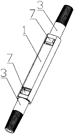
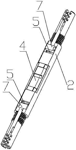
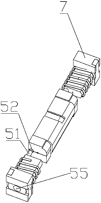
[0027] As shown in the figure, an optical cable connector includes a housing 1, a main body 2, and a boot 3 docked with both ends of the main body 2. The housing 1 wraps the main body 2 in the axial direction, and the main body 2 is hollow and A built-in clamping mechanism 4 is provided, and the two ends of the clamping mechanism 4 are provided with an introduction piece 5 embedded in the main body 2 and capable of reciprocating sliding movement along the length direction of the main body 2. The clamping mechanism 4 has a The introduction part 5 is inserted into the clamping mechanism 4 along the length direction in the first state and is stretched for the optical cable to enter, and the second state in which the introduction part 5 tightly clamps the optical cable after exiting the clamping mechanism 4, the introduction part 5 is fixed with a push buckle 7 ...


PUM


Abstract

The invention discloses a cable adapter, and relates to the technical field of optical fiber communication. The cable adapter comprises an outer shell, a main body and a tail sleeve abutted with bothheads of the main body; the outer shell coats the main body along axial direction, and the main body is hollow and provided with a built-in clamping mechanism; both ends of the clamping mechanism areprovided with import pieces embedded in the main body and capable of performing reciprocated slippery movement along the length direction of the main body; the clamping mechanism is provided with a first state where the import piece is inserted to the clamping mechanism along the length direction and opened to make a cable enter and a second state where the import piece retreats the clamping mechanism and then tightly clamps the cable; a push buckle exposed at outside of the outer shell is fixedly arranged on the import piece. The cable adapter has the advantages of simplifying user operationand expanding product using environment, and being good in product quality and long in service life.

Description

technical field [0001] The invention relates to the technical field of optical fiber communication, in particular to an optical cable butt joint. Background technique [0002] Driven by FTTB and FTTH, when reaching the last mile of the end user, the use of two optical fibers or optical cables is increasing year by year. Under the condition of ensuring the quality of the connection, the cost and convenience have become the major operators at home and abroad. and the concerns of builders. There are two types of joints in this field: welding and cold jointing. The welding method is costly and requires high skill proficiency of the operator, but the cold welding method has great advantages, such as low raw material cost, low use cost, less strict requirements on the site environment and easy operation. [0003] People in the industry collectively refer to such products in the market as "fiber optic cold splices". The optical fiber clamping method is generally clamped by foldin...

Claims


Application Information

Patent Timeline
Patent Type & Authority Applications(China)
IPC IPC(8): G02B6/38
CPCG02B6/3838
Inventor 卢立建董永成华培萱刘红宇
Owner 湖南中科光电有限公司
Why Eureka
Try Eureka