Developing unit, treating box and electronic imaging device

A developing unit and developing roller technology, applied in the field of developing unit, processing box and electronic imaging device, can solve the capacity loss of the waste toner recovery bin in the developing chamber, reduce the production efficiency of the processing box, complex structures of the developing shell and the photosensitive shell, etc. problems, to achieve the effects of reduced occupation, good developing performance, and reduced capacity loss

Active Publication Date: 2018-06-12
ZHUHAI PANTUM ELECTRONICS
View PDF6 Cites 0 Cited by
  • Summary
  • Abstract
  • Description
  • Claims
  • Application Information

AI Technical Summary

Problems solved by technology

[0006] However, in the existing process cartridges, both the developing housing and the photosensitive housing need to be provided with an installation structure for installing the pushing mechanism, resulting in more complex structures of the developing housing and the photosensitive housing, reducing the development housing and the photosensitive housing. The ejection efficiency of the photosensitive housing reduces the production efficiency of the process cartridge
Moreover, since a certain installation space needs to be reserved between the rear side of the developing housing and the rear side of the photosensitive housing to install the spring, this has caused the waste toner recovery of the developing chamber at the rear side of the developing housing or the rear side of the photosensitive housing. The capacity loss of the bin, this problem is particularly prominent when the device needs to be miniaturized

Method used


Image

  • Developing unit, treating box and electronic imaging device
  • Developing unit, treating box and electronic imaging device
  • Developing unit, treating box and electronic imaging device

Examples


Embodiment 1

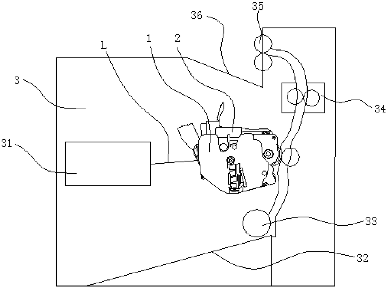
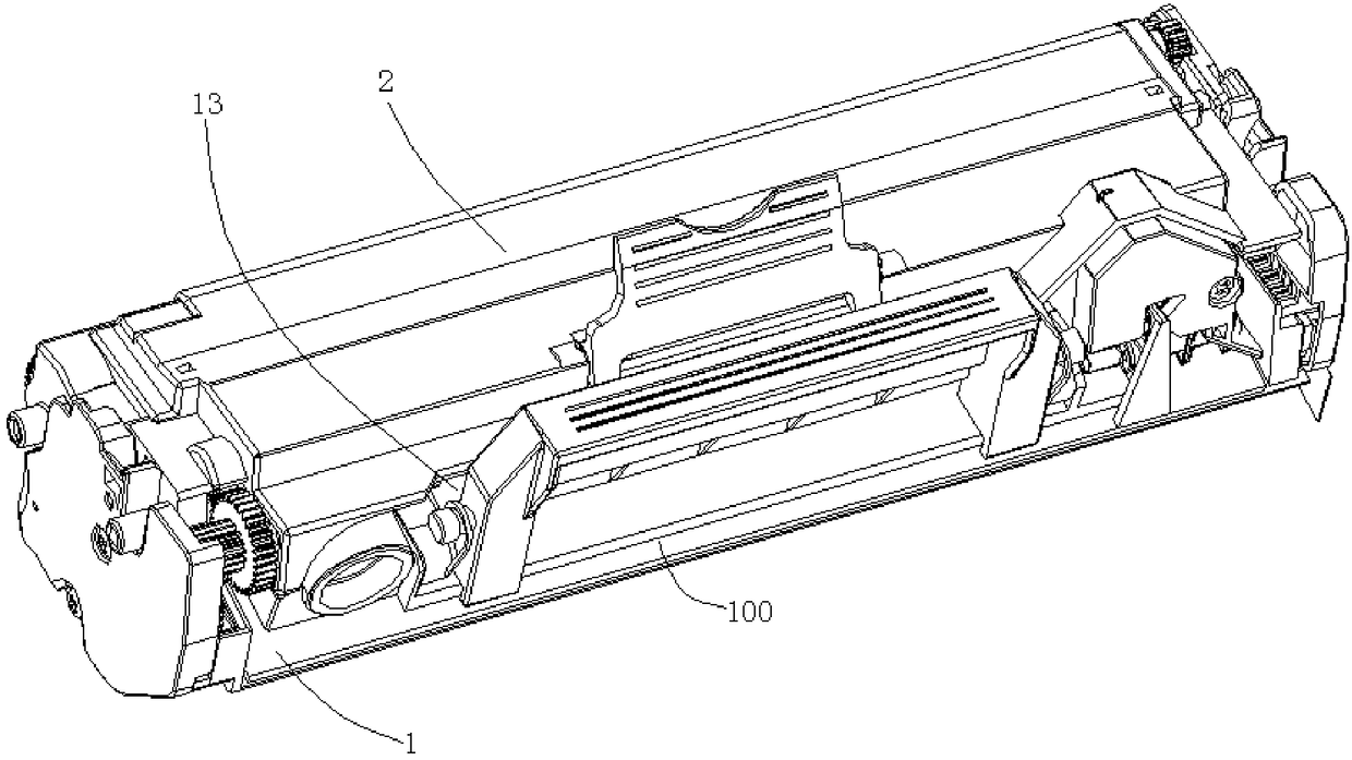
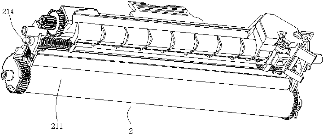
[0052] figure 2 It is a schematic structural diagram of a process cartridge including the developing unit provided in the first embodiment; image 3 It is a schematic structural diagram of the photosensitive unit assembled with the developing unit provided in the first embodiment; Figure 4 A schematic structural diagram of the developing unit provided in the first embodiment; Figure 5 for Figure 4 Put in a zoomed-in schematic.

[0053] Image 6 A cross-sectional view before the developing unit and the photosensitive unit provided in the first embodiment are not assembled in place; Figure 7 A cross-sectional view when the developing unit and the photosensitive unit provided in the first embodiment are assembled in place; Figure 8 This is a schematic diagram of the force between the abutting portion and the photosensitive unit in the developing unit provided in the first embodiment.

[0054] Figure 9 A schematic diagram of the installation of the forcing component ...

Embodiment 2

[0081] Figure 15 This is a schematic structural diagram of the developing unit and the photosensitive unit provided in the second embodiment.

[0082] Please refer to Figure 15 , this embodiment provides a developing unit 1. The difference between the developing unit 1 provided by this embodiment and the first embodiment is that in the developing unit 1 of this embodiment, the elastic member is a compression spring 1312, and the compression spring 1312 is arranged in the Below the support arm 1321 , the compression spring 1312 is specifically abutted between the lower surface of the support arm 1321 and the developing casing 11 .

[0083] Of course, the elastic member can also be an elastic protrusion extending downward from the bottom of the support arm 1321 , and the elastic protrusion also abuts against the developing casing 11 . In this embodiment, the developing unit 1 is described by taking the elastic member as the compression spring 1312 as an example.

[0084] Wh...


PUM


Abstract

The invention relates to imaging techniques, in particular to a developing unit, a treating box and an electronic imaging device. A pushing component is rotationally connected with a developing shell,a butting portion in the pushing component is abutted to a light-sensing shell, and therefore, the pushing component has greater setting space outside the developing shell at the premise that a light-sensing drum is in tight contact or mutually close to a developing roller, and space of a developing chamber in the developing shell is reduced for use to greater extent; the space of a waste powderrecycling chamber in the light-sensing shell is not necessarily used, and therefore, capacity loss is greatly reduced for the developing chamber and the waste powder recycling chamber.

Description

technical field [0001] The present invention relates to image forming technology, in particular to a developing unit, a process cartridge and an electronic imaging device. Background technique [0002] Electronic imaging devices such as laser printers, copiers, printing presses, etc., are a kind of equipment that forms images on image media such as paper, generally including: an imaging device main body and a process cartridge, the process cartridge is detachably installed in the imaging device main body; imaging The main body of the device is used to acquire print data and convert it into corresponding laser signals; the process cartridge is used to develop and image according to the laser signals. [0003] In order to realize developing and imaging, the process cartridge usually includes: a developing unit and a photosensitive unit, and the developing unit and the photosensitive unit are rotatably connected by a rotating shaft. The developing unit specifically includes a ...

Claims


Application Information

Patent Timeline
IPC IPC(8): G03G21/16G03G21/18
CPCG03G21/1647G03G21/1671G03G21/1676G03G21/1814
Inventor 龚海飞曹玉兵
Owner ZHUHAI PANTUM ELECTRONICS
Why Eureka
Try Eureka