

Power module clock synchronization circuit
A power module and clock synchronization technology, which is applied in the direction of electrical components, output power conversion devices, etc., can solve problems such as difficult implementation and complex circuits, and achieve high reliability, simple circuit drive, and avoid false conduction effects
- Summary
- Abstract
- Description
- Claims
- Application Information
AI Technical Summary
Problems solved by technology
Method used
Image

Examples
Embodiment Construction
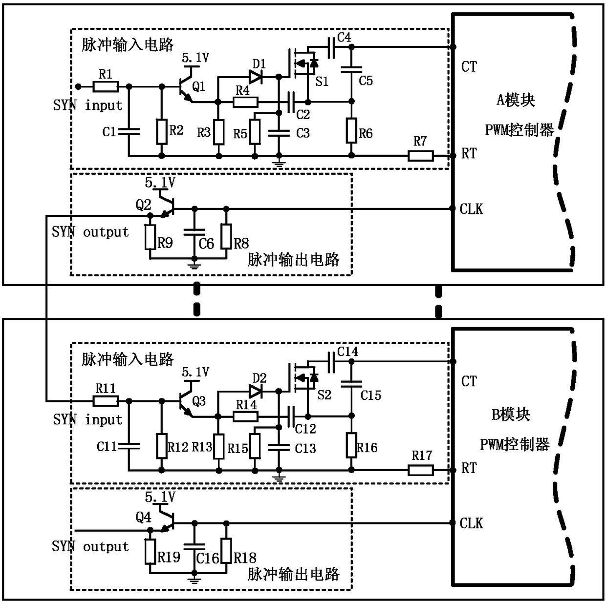
[0020] The basic idea of the present invention is: a power module clock synchronization circuit, including: a PWM controller, a pulse input circuit and a pulse output circuit in each power module, and the PWM controller, pulse input circuit and pulse output of the power module The circuit forms a power module group; connect at least two power module groups in parallel in the circuit. Compared with the prior art, this parallel power supply clock synchronization method adopts logic level MOS transistors for clock synchronization in the pulse input circuit, which effectively enhances the circuit's anti-interference ability. The clock synchronization circuit is realized by discrete components such as diodes and MOS tubes, with simple circuit, high reliability, low cost and strong practicability.
[0021] The present invention connects the pulse input circuit and the pulse output circuit to each power module PWM controller, the power module PWM controller, the pulse input circuit an...
PUM
 Abstract
Description
Claims
Application Information