
Sterilization device for textile processing

A disinfection device and textile technology, applied in the textile field, can solve the problems of no humidity sensor, odor elimination, and inability to detect the humidity of the disinfection cabinet body, so as to achieve the effect of ensuring a normal disinfection environment

Inactive Publication Date: 2018-06-15
响水县嘉禾纺织制衣有限公司
View PDF0 Cites 4 Cited by
  • Summary
  • Abstract
  • Description
  • Claims
  • Application Information

AI Technical Summary

Problems solved by technology

[0002] Textile is a handicraft industry that serves human clothing. Spinning and weaving, making clothes, hiding ugliness and beauty, protecting the body from cold and wind, and protecting the body from insects are probably important motives for the origin and development of textiles. In the late period, budding has been seen. About 20,000 years ago, the cavemen in Beijing learned to use bone needles to sew reeds and leather clothes. However, in the process of textile production, the disinfection of textiles is a technical problem that still needs technological innovation.
[0003] However, the textile processing and disinfection devices currently on the market have complex structures and single functions. There is no clean room, and it is impossible to purify the air and eliminate odors inside the disinfection cabinet body. There are no shelves and ventilation holes, and textiles cannot be fully disinfected. , without an ultrasonic humidifier, the textiles inside the disinfection cabinet cannot be atomized and sterilized, without a humidity sensor, the humidity in the disinfection cabinet cannot be detected, and without a heating chamber, the humid environment of the disinfection cabinet cannot be sterilized. drying effect

Method used


Image

  • Sterilization device for textile processing
  • Sterilization device for textile processing
  • Sterilization device for textile processing

Examples


Embodiment

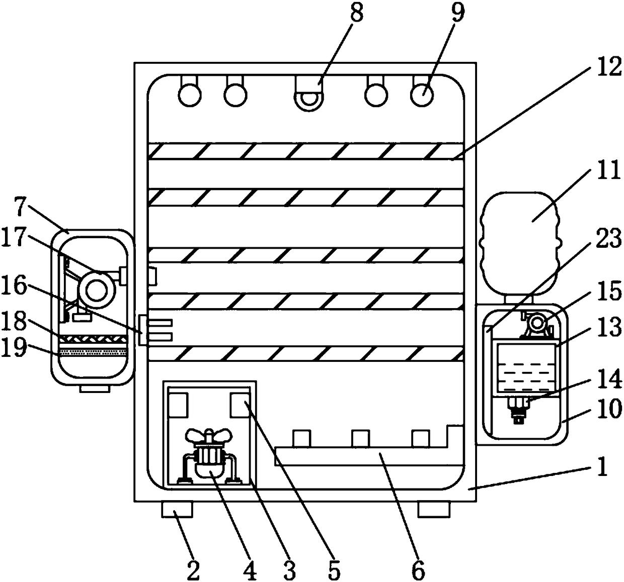
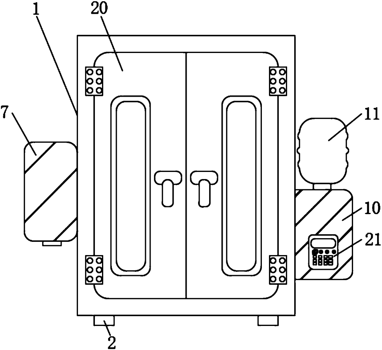
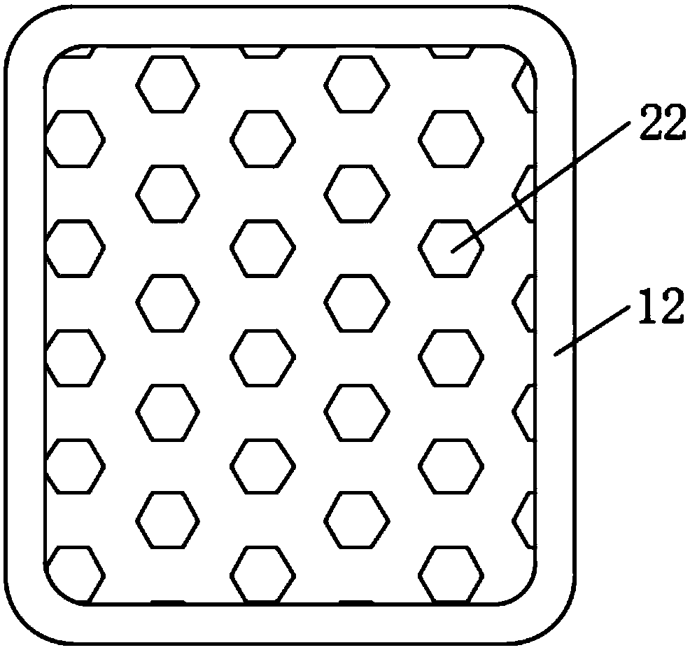
[0021] Example: such as Figure 1-3 As shown, the present invention provides a technical solution, a disinfection device for textile processing, comprising a disinfection cabinet body 1, the lower end of the disinfection cabinet body 1 is provided with a support 2, and the inner bottom of the disinfection cabinet body 1 is provided with Heating chamber 3, the inside of the disinfection cabinet body 1 is provided with a shelf 12 close to the upper position of the heating chamber 3, and the inner lower position of the disinfection cabinet body 1 is provided with a second nozzle 6 near the side of the heating chamber 3 for disinfection. The inner top of the cabinet body 1 is provided with a lighting lamp 8, and the side of the inner top of the disinfection cabinet body 1 near the lighting lamp 8 is provided with an ultraviolet disinfection lamp 9, and one side of the disinfection cabinet body 1 is provided with a clean room 7, and the disinfection cabinet body The other side of t...


PUM


Abstract

The invention discloses a sterilization device for textile processing. The sterilization device comprises a sterilization cabinet body, wherein a heating chamber is formed in the bottom inside the sterilization cabinet body; a holding plate is arranged above a part close to the heating chamber inside the sterilization cabinet body; a purification chamber is formed in one side of the sterilizationcabinet body; an ultrasonic humidifier is arranged on another side of the sterilization cabinet body; a humidity sensor is embedded in a position on the side close to the purification chamber on the inner wall of the sterilization cabinet body. Due to adoption of the purification chamber, air quality inside the sterilization cabinet body is ensured; due to adoption of the holding plate and vent holes, the purposes that a textile is placed and sterilized and disinfected by a user can be achieved; due to adoption of the humidity sensor and the heating chamber, the phenomenon that damage can be caused by a long-term over-wet state of the textile is avoided; due to adoption of the ultrasonic humidifier, the textile inside the sterilization cabinet body can be sterilized and disinfected, and anormal sterilization environment can be ensured for the textile.

Description

technical field [0001] The invention relates to the technical field of textiles, in particular to a disinfection device for textile processing. Background technique [0002] Textile is a handicraft industry that serves human clothing. Spinning and weaving, making clothes, hiding ugliness and beauty, protecting the body from cold and wind, and protecting the body from insects are probably important motives for the origin and development of textiles. In the late period, budding has been seen. About 20,000 years ago, the cavemen in Beijing learned to use bone needles to sew reeds and leather clothes. However, in the process of textile production, the disinfection of textiles is a technical problem that still needs technological innovation. . [0003] However, the textile processing and disinfection devices currently on the market have complex structures and single functions. There is no clean room, and it is impossible to purify the air and eliminate odors inside the disinfect...

Claims


Application Information

Patent Timeline
IPC IPC(8): A61L2/10A61L2/07A61L2/025A61L2/26A61L9/16
CPCA61L2/10A61L2/025A61L2/07A61L2/26A61L9/16A61L2202/14A61L2202/26
Inventor 顾秀平
Owner 响水县嘉禾纺织制衣有限公司
Features
  • Generate Ideas
  • Intellectual Property
  • Life Sciences
  • Materials
  • Tech Scout
  • Unparalleled Data Quality
  • Higher Quality Content
  • 60% Fewer Hallucinations
Learn More