Guardrail bending device

A bending device and guardrail technology, applied in metal processing equipment, forming tools, manufacturing tools, etc., can solve the problems of difficult control of the bending angle, easy to break, etc., to save manpower, avoid excessive rigidity, and improve the effect of forming rate

Active Publication Date: 2018-06-15
临沂经济开发有限公司
View PDF6 Cites 6 Cited by
  • Summary
  • Abstract
  • Description
  • Claims
  • Application Information

AI Technical Summary

Problems solved by technology

[0003] The purpose of the present invention is to provide a guardrail bending device to solve the problem that the bending angle of the guardrail bending device in the prior art is not easy to control and is prone to breakage during the bending process

Method used


Image

  • Guardrail bending device
  • Guardrail bending device

Examples


Embodiment Construction

[0013] The present invention will be described in further detail below by means of specific embodiments:

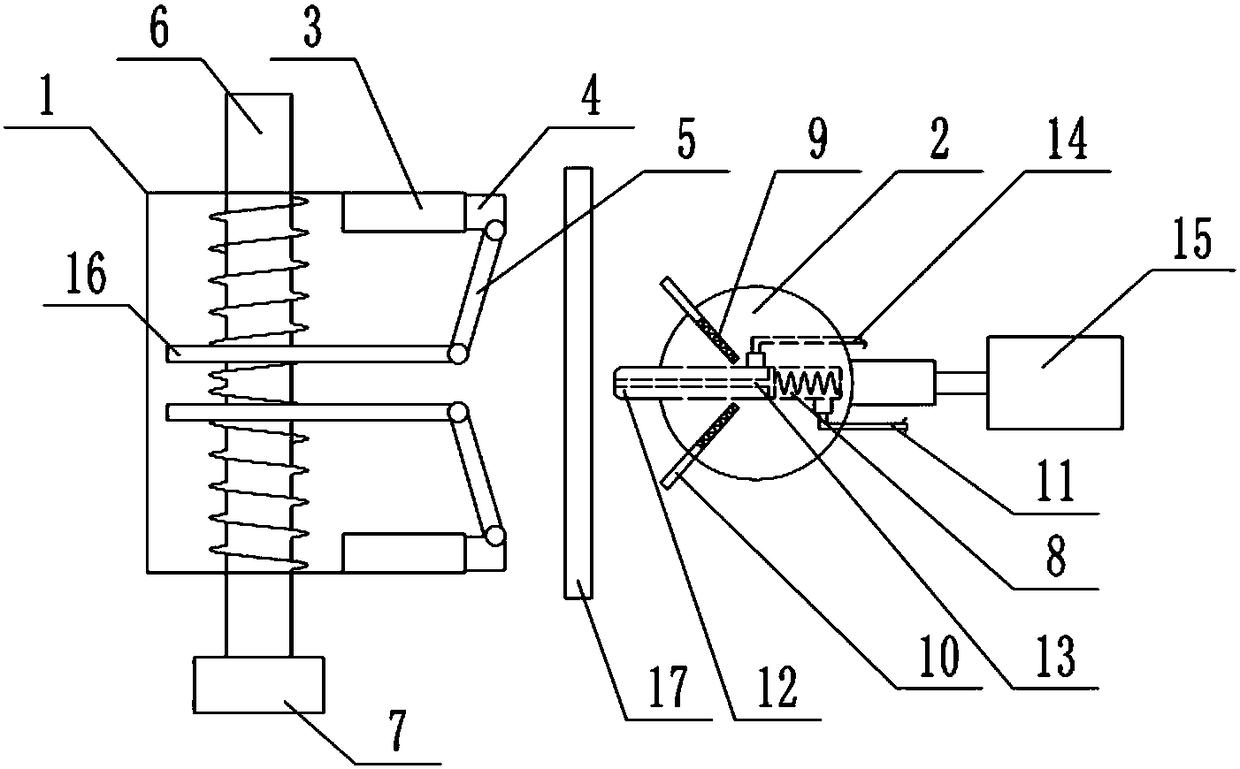
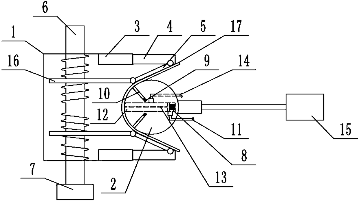
[0014] The reference signs in the drawings of the description include: positioning frame 1, bending roller 2, sliding seat 3, sliding plate 4, rotating plate 5, screw rod 6, motor 7, horizontal chute 8, chute 9, inclined plate 10, heating pipe 11. Contact 12, air outlet pipe 13, cooling pipe 14, hydraulic cylinder 15, support plate 16, guardrail 17.

[0015] Such as figure 1 , figure 2 As shown, a guardrail bending device includes in turn a horizontal positioning frame 1, a bending roller 2, and a first power mechanism that pushes the bending roller 2 to move along the center line of the positioning frame 1. The first power mechanism is a hydraulic cylinder 15, and the hydraulic pressure The piston rod of the cylinder 15 is fixedly connected with the bending roller 2; two sliding seats 3 are symmetrically connected by bolts on both sides of the positioning frame 1, and...


PUM


Abstract

The invention belongs to the technical field of guardrail machining, and particular discloses a guardrail bending device. The guardrail bending device sequentially comprises a horizontally-placed positioning frame, a bending roll and a first power mechanism; sliding seats are symmetrically arranged on the two sides of the positioning frame, sliding plates are horizontally and slidably connected into the sliding seats, and the positioning frame is internally provided with two supporting plates and a second power mechanism; rotating plates are connected between the supporting plates and the sliding plates, one ends of the rotating plates are hinged to the supporting plates, and the other ends of the rotating plates are hinged to the sliding plates; and the bending roll is fixedly connected with the first power mechanism and is internally provided with a horizontal sliding chute and two oblique grooves, openings of the horizontal sliding chute and the oblique grooves face the positioningframe, and the horizontal sliding chute is internally provided with a heating mechanism. When a guardrail is extruded by the bending roll, the heating mechanism heats the to-be-bent position of the guardrail, and oblique plates are slidably connected into the oblique grooves. According to the guardrail bending device, the bending angle is easily controlled, and breaking does not easily occur in the bending process.

Description

technical field [0001] The invention belongs to the technical field of guardrail processing, and specifically discloses a guardrail bending device. Background technique [0002] In the process of guardrail processing, it is usually necessary to bend the guardrail at a certain angle to meet the needs of laying. The existing guardrail bending process mostly uses bending devices for manual processing. The bending angle of the guardrail is not easy to control, and in the bending process prone to breakage. Contents of the invention [0003] The purpose of the present invention is to provide a guardrail bending device to solve the problem that the bending angle of the guardrail bending device in the prior art is difficult to control and is prone to breakage during the bending process. [0004] In order to achieve the above object, the basic solution of the present invention is: a guardrail bending device, which successively includes a horizontally placed positioning frame, a be...

Claims


Application Information

Patent Timeline
Patent Type & Authority Applications(China)
IPC IPC(8): B21D7/06B21D37/16
CPCB21D7/06B21D7/162B21D37/16
Inventor 周琪周强
Owner 临沂经济开发有限公司
Why Eureka
Try Eureka