A high-efficiency steel plate derusting device for construction sites

A construction site, high-efficiency technology, applied in the direction of grinding drive devices, manufacturing tools, metal processing equipment, etc., can solve the problems of wasting time, loss, waste, etc., to reduce mechanical connections, simple and reasonable structure, and improve rust removal effect Effect

Active Publication Date: 2019-11-29
烟台大兴钢结构有限公司
View PDF3 Cites 0 Cited by
  • Summary
  • Abstract
  • Description
  • Claims
  • Application Information

AI Technical Summary

Problems solved by technology

[0003] Among them, steel plate is one of the building materials commonly used on construction sites, because most of the construction sites are set up in the sky, so these steel plates are easily oxidized to make the surface rust, and in actual use, the rust on the surface of the steel plate The trace needs to be removed. Traditionally, it is manually polished with sandpaper, which is a waste of time. Later, a rust remover appeared, which can move the metal brush on the surface of the steel plate through simple mechanical movement to remove rust. , but the structure of the existing rust remover that drives the movement of the metal brush often needs to change the moving direction of the brush through some transmissions or bevel gears, and the force will be lost in the process of transmission through the transmission and bevel gears Therefore, there is a certain waste and needs to be improved

Method used


Image

  • A high-efficiency steel plate derusting device for construction sites
  • A high-efficiency steel plate derusting device for construction sites
  • A high-efficiency steel plate derusting device for construction sites

Examples


Embodiment Construction

[0018] The technical solution of this patent will be further described in detail below in conjunction with specific embodiments.

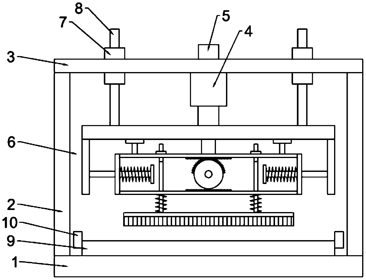
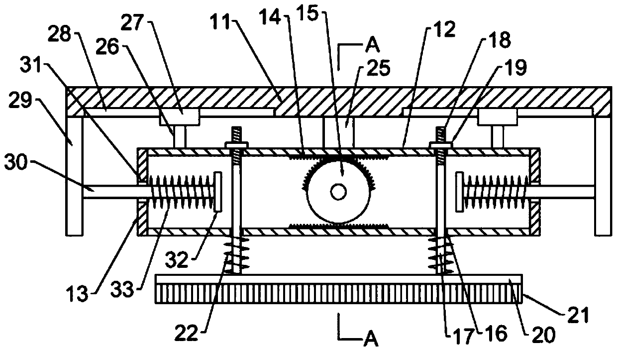
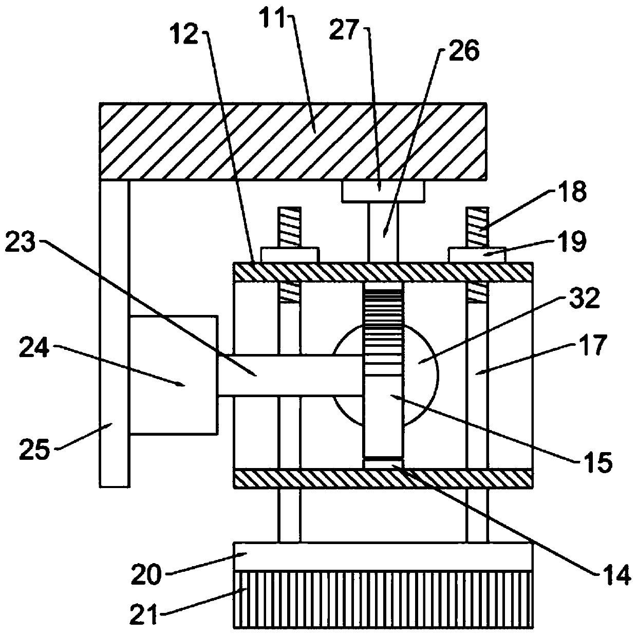
[0019] see Figure 1-4 , a high-efficiency steel plate derusting device for a construction site, comprising a base 1, a support column 2 is installed at the four corners of the upper end of the base 1, a top plate 3 is installed on the upper end of the support column 2, a lifting mechanism 4 is installed at the center of the lower end of the top plate 3, and the top plate The center of the upper end of 3 is equipped with a power unit 5 that provides power for the lifting mechanism 4, and the lower end of the lifting mechanism 4 is equipped with a derusting mechanism 6, and a working platform 9 is installed on the base 1 directly below the derusting mechanism 6, and the working platform 9 There is also a clamp 10 on the top, the derusting mechanism 6 includes a mounting plate 11, the mounting plate 11 is parallel to the top plate 3, the center of th...


PUM


Abstract

The invention discloses an efficient steel plate rust removal device for a construction site. The efficient steel plate rust removal device comprises a base, support columns, a top plate, a lifting mechanism, a power device, a dust removal mechanism and a working platform. The rust removal mechanism comprises a mounting plate, horizontal plates, a vertical plate, racks, a semi-circular gear, firstthrough holes, pressure rods, threaded parts, bolts, a pressure plate and a hairbrush. Compression springs are arranged between the pressure plate and the horizontal plates below the pressure plate.Connecting rods are mounted at the upper end of a mounting frame. A sliding block is mounted at the top end of each connecting rod. Sliding grooves are formed in the lower end face of the mounting plate. The upper end of each sliding block is slidably arranged in the corresponding sliding groove. According to the efficient steel plate rust removal device, the pressure plate and the hairbrush belowthe mounting frame can be driven by the semi-circular gear to perform dust removal on the surface of the steel plate arranged on the working platform, and the moving direction of the semi-circular gear in the entire process is constant, so that no connecting mechanism for changing the direction is needed, mechanical connection is omitted, and no control and change in the steering of a motor is needed.

Description

technical field [0001] The invention relates to a rust remover, in particular to a high-efficiency steel plate rust remover for construction sites. Background technique [0002] A construction site is a place where construction projects are being developed and civil engineering is carried out. Its scope is often closed by hoardings, barbed wire or walls, restricting the entry and exit of personnel, materials, machinery and vehicles, and guarded by property management administrators. You may need to register your identity and wear a helmet when entering and exiting. Construction sites often have stockpiles of building materials, which is a collective term for materials used in civil engineering and construction. It can be divided into structural materials, decorative materials and some special materials. Structural materials include wood, bamboo, stone, cement, concrete, metal, brick, ceramics, glass, engineering plastics, composite materials, etc. [0003] Among them, ste...

Claims


Application Information

Patent Timeline
Patent Type & Authority Patents(China)
IPC IPC(8): B24B27/033B24B41/06B24B47/04
CPCB24B27/033B24B41/06B24B47/04
Inventor 陆江斌
Owner 烟台大兴钢结构有限公司
Why Eureka
Try Eureka