Forming device for aerospace composite material

A composite material and molding device technology, applied in the aerospace field, can solve the problems of large vibration amplitude, very high molding device requirements, and large impact on finished products, and achieve the effect of reducing vibration

Inactive Publication Date: 2018-06-15
ZHONGSHAN DEGAOXING INTPROP CENT LLP
View PDF4 Cites 4 Cited by
  • Summary
  • Abstract
  • Description
  • Claims
  • Application Information

AI Technical Summary

Problems solved by technology

So far, although aerospace activities are only the first few steps of human beings leaving the cradle of the earth, their functions have gone far beyond the field of science and technology, and have had extensive and far-reaching impacts on politics, economy, military affairs and even human social life. , in the field of aerospace, a variety of composite materials are often used, so the requirements for these materials are very high, so the requirements for the corresponding forming devices are also very high. Among them, in the stamping process, the existing technology The stamping structure is relatively simple, and the vibration amplitude is relatively large, which has a great impact on the finished product. Therefore, we propose a forming device for aerospace composite materials to solve the above problems

Method used


Image

  • Forming device for aerospace composite material
  • Forming device for aerospace composite material
  • Forming device for aerospace composite material

Examples


Embodiment Construction

[0019] The following will clearly and completely describe the technical solutions in the embodiments of the present invention with reference to the accompanying drawings in the embodiments of the present invention. Obviously, the described embodiments are only some, not all, embodiments of the present invention. Based on the embodiments of the present invention, all other embodiments obtained by persons of ordinary skill in the art without making creative efforts belong to the protection scope of the present invention.

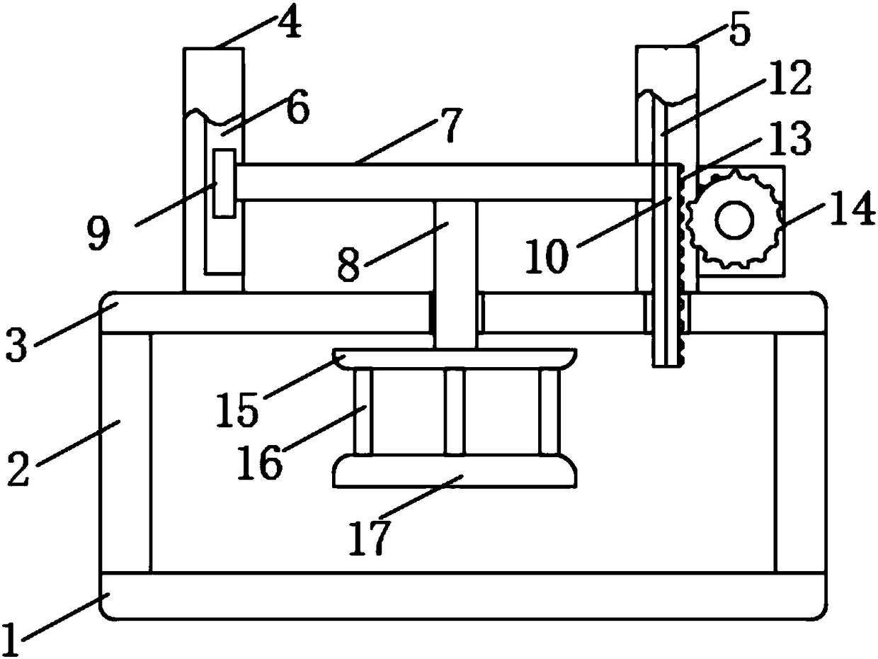
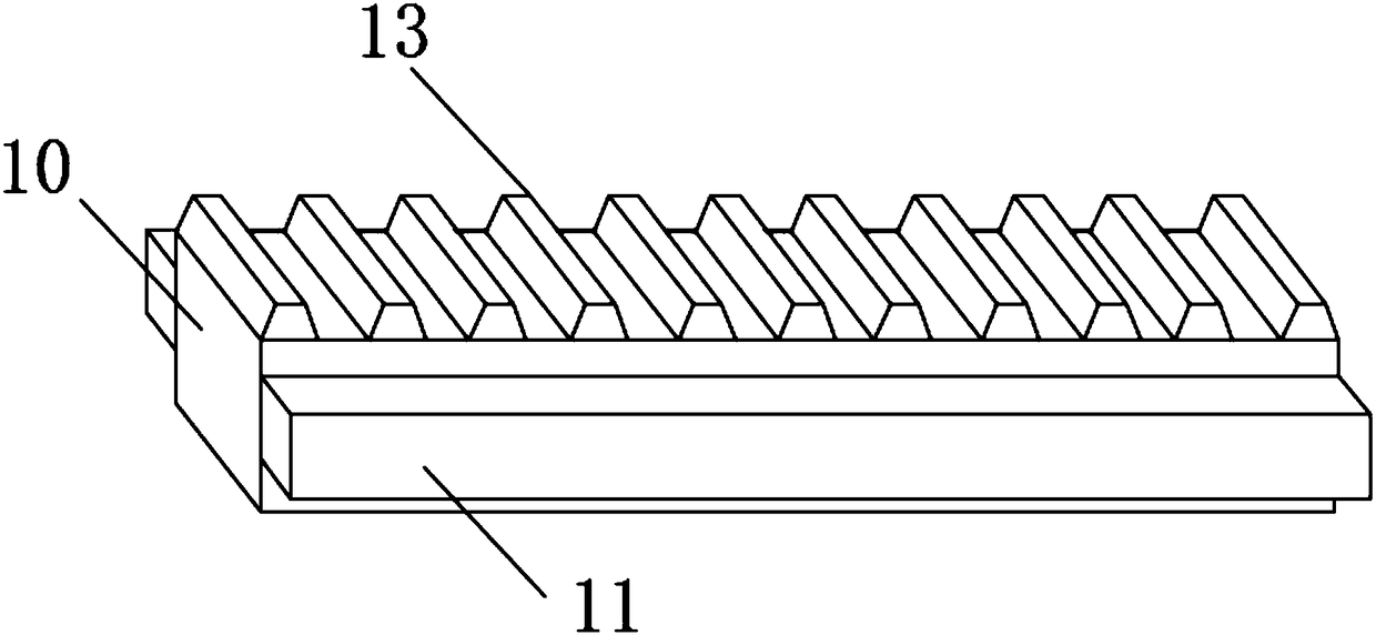
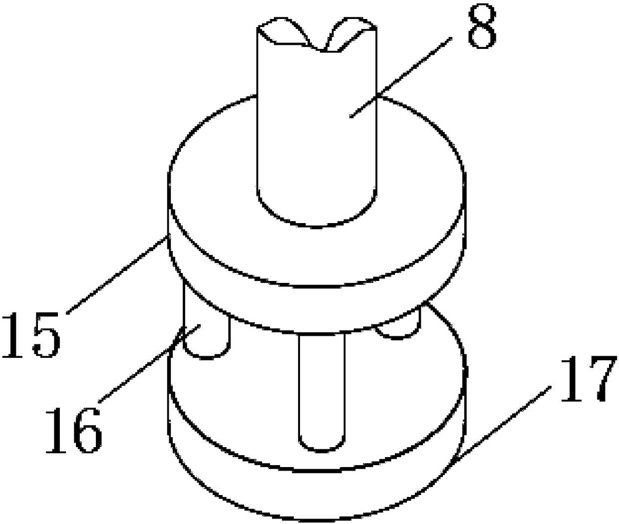
[0020] see Figure 1-3 , the present invention provides a technical solution: a molding device for aerospace composite materials, including a base 1 and a mounting seat 3, the upper surface of the base 1 is symmetrically welded vertically and provided with a support column 2, and the ends of the support column 2 are fixed Welding is provided with mounting base 3, one side of mounting base 3 is vertically provided with positioning base 4, and the inside of posi...


PUM


Abstract

The invention discloses a forming device for an aerospace composite material. The forming device comprises a base and an installing base. Supporting columns are symmetrically arranged on the upper surface of the base in a vertically welded manner. An installing base is fixedly arranged on the end portions of the supporting columns in a welded manner. A locating base is vertically arranged on one side of the installing base. A locating groove is formed in the locating base. The supporting columns are symmetrically arranged on the upper surface of the base, the installing base is arranged abovethe supporting columns, the locating base and a moving base are arranged on the two sides of the installing base correspondingly, meanwhile, a locating block arranged on the end portion of a moving rod is arranged in the locating base in a sliding manner, and thus, the moving rod is relatively stable when moving. A moving plate arranged on the end portion of the moving rod is arranged in the moving base, thus, vibration generated in the working process of the structure is not distributed to the edge as much as possible, and pressurizing can be carried out better. Sliding blocks are symmetrically arranged on the two sides of the moving plate and arranged in sliding grooves in a sliding manner, and thus when the moving plate moves, the vibration is reduced as much as possible.

Description

technical field [0001] The invention relates to the field of aerospace technology, in particular to a molding device for aerospace composite materials. Background technique [0002] The development of the aerospace industry is the result of the rapid progress of science and technology and the rapid development of social production in the 20th century. The achievements of aerospace have concentrated many new achievements in science and technology. So far, although aerospace activities are only the first few steps of human beings leaving the cradle of the earth, their functions have gone far beyond the field of science and technology, and have had extensive and far-reaching impacts on politics, economy, military affairs and even human social life. , in the field of aerospace, a variety of composite materials are often used, so the requirements for these materials are very high, so the requirements for the corresponding forming devices are also very high. Among them, in the st...

Claims


Application Information

Patent Timeline
Patent Type & Authority Applications(China)
IPC IPC(8): B29C43/34B29C43/32B29L31/30
CPCB29C43/32B29C43/34B29L2031/3076B29L2031/3097
Inventor 谢小坚梁荣强
Owner ZHONGSHAN DEGAOXING INTPROP CENT LLP
Why Eureka
Try Eureka