
Material clamping mechanism of automatic charging device

An automatic feeding and retrieving mechanism technology, which is applied to the surface coating liquid device, conveyor objects, transportation and packaging, etc., can solve the problems of low production efficiency of automatic assembly line, dense processing equipment placement, high labor intensity of workers, etc. problems, to achieve the effect of realizing mechanical automation production, ensuring automatic feeding, and improving efficiency

Active Publication Date: 2018-06-15
宁波优耐特模具有限公司
View PDF2 Cites 0 Cited by
  • Summary
  • Abstract
  • Description
  • Claims
  • Application Information

AI Technical Summary

Problems solved by technology

However, in traditional mechanical processing and manufacturing, many workpieces are still operated by manual loading. Relying on manual loading not only greatly reduces the production efficiency of the automatic assembly line, but even causes defective products. The labor intensity of workers is high and limited by space. The processing equipment is densely placed, and the workpieces are placed in piles beside the equipment, which makes the production environment chaotic and poses certain safety hazards

Method used


Image

  • Material clamping mechanism of automatic charging device
  • Material clamping mechanism of automatic charging device
  • Material clamping mechanism of automatic charging device

Examples


Embodiment Construction

[0013] The present invention will be further described below in conjunction with the accompanying drawings and embodiments.

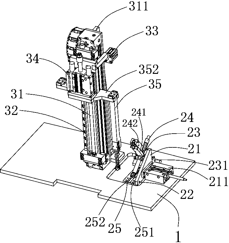
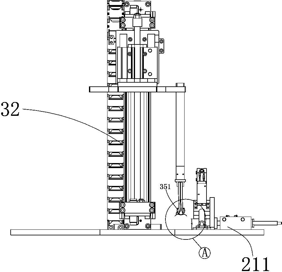
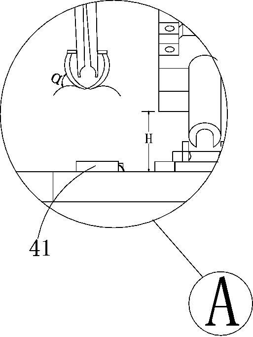
[0014] see Figure 1 to Figure 3 , a clamping mechanism of an automatic feeding device, including a workbench 1, on which a reclaiming mechanism, an air blowing mechanism and a feeding mechanism arranged on one side of the reclaiming mechanism are arranged, the feeding mechanism It includes a cylinder vertical plate 21 arranged perpendicular to the workbench 1, and a signal switch 22 is arranged on the cylinder vertical plate 21. There is a gap H between the platforms 1, the aisle 24 fixed by the pressing mechanism 241 and with the blocking mechanism 242 is arranged on the inclined plate 23, and the receiving slot 25 with the symmetrical air hole 251 is correspondingly provided directly below the end of the aisle 24, The workpiece pushing mechanism 231 disposed behind the inclined plate 23 can pass through the gap between the inclined plate 23 and the ...


PUM


Abstract

The invention discloses a material clamping mechanism of an automatic charging device. The material clamping mechanism comprises a workbench; a material taking mechanism, an air blowing mechanism, anda feeding mechanism which is arranged on one side of the material taking mechanism are arranged on the workbench; a mechanical arm driven by a driving device is arranged at the front end of a rodlessair cylinder; a protective device is hinged to the mechanical arm; the protective device comprises block pieces symmetrically arranged on the two sides of the mechanical arm; each block piece is provided with two arc-shaped structures; the two block pieces are arranged reversely; and an included angle alpha is formed between the two block pieces. With the adoption of the structure, automatic charging can be ensured, and the charging can not be affected in the charging process when a workpiece falls off; when a working section is far, the feeding stroke can be increased through the rodless aircylinder; and with the adoption of the mechanical mode, the charging is accelerated, the efficiency is improved, a factory is liberated from heavy manual labor, the manpower cost is lowered, mechanical automation production of the factory is realized and potential safety hazards in manual charging are avoided directly.

Description

technical field [0001] The invention relates to the technical field of mechanical transmission, in particular to a clamping mechanism of an automatic feeding device. Background technique [0002] Automation technology is widely used in industry, agriculture, military, scientific research, transportation, commerce, medical care, services and households. The use of automation technology can not only liberate people from heavy manual labor, part of mental labor and harsh and dangerous working environments, but also expand human organ functions, greatly improve labor productivity, and enhance human ability to understand and transform the world . However, in the traditional mechanical processing and manufacturing, many workpieces still adopt the manual feeding operation method. Relying on manual feeding not only greatly reduces the production efficiency of the automatic assembly line, but also causes defective products. The labor intensity of workers is high, and due to space co...

Claims


Application Information

Patent Timeline
Patent Type & Authority Applications(China)
IPC IPC(8): B65G47/82B65G47/88B65G47/90B05C1/02B08B1/02B08B1/20
CPCB65G47/82B65G47/8815B65G47/901B05C1/02B08B1/20
Inventor 徐波杰张峰李涛
Owner 宁波优耐特模具有限公司
Learn More