
Tension-feeding and die-cutting automatic embroidering machine and operation method thereof

A technology for feeding dies and embroidery machines, which is applied in the direction of automatic control embroidery machines, embroidery machines, embroidery machine mechanisms, etc., which can solve the problems of long cutting cycle, high alignment accuracy requirements, cumbersome operation, etc. Cutting precision, high cutting precision of pressing shape, and the effect of ensuring product quality

Pending Publication Date: 2018-06-15
严伟强
View PDF0 Cites 4 Cited by
  • Summary
  • Abstract
  • Description
  • Claims
  • Application Information

AI Technical Summary

Problems solved by technology

[0004] 1. Feeding and receiving materials are usually manually operated, which is complicated and affects embroidery efficiency
[0005] 2. Most of the fabric tensioning procedures are achieved by manually clamping the four sides of the fabric with clamps. The operation is cumbersome and labor-intensive, and the tension degree is controlled by the operator based on experience. It is difficult to adjust according to the texture of the fabric. Controlling the tension of the fabric will reduce the embroidery precision and affect the embroidery quality
[0006] 3. The cutting part of the existing embroidery machine generally uses laser cutting or hot knife cutting. Laser cutting and hot knife cutting require high alignment accuracy, long cutting cycle, high production cost, and even shrinkage of the processed material during the cutting process. , it is impossible to complete the cutting

Method used


Image

  • Tension-feeding and die-cutting automatic embroidering machine and operation method thereof
  • Tension-feeding and die-cutting automatic embroidering machine and operation method thereof
  • Tension-feeding and die-cutting automatic embroidering machine and operation method thereof

Examples


Embodiment Construction

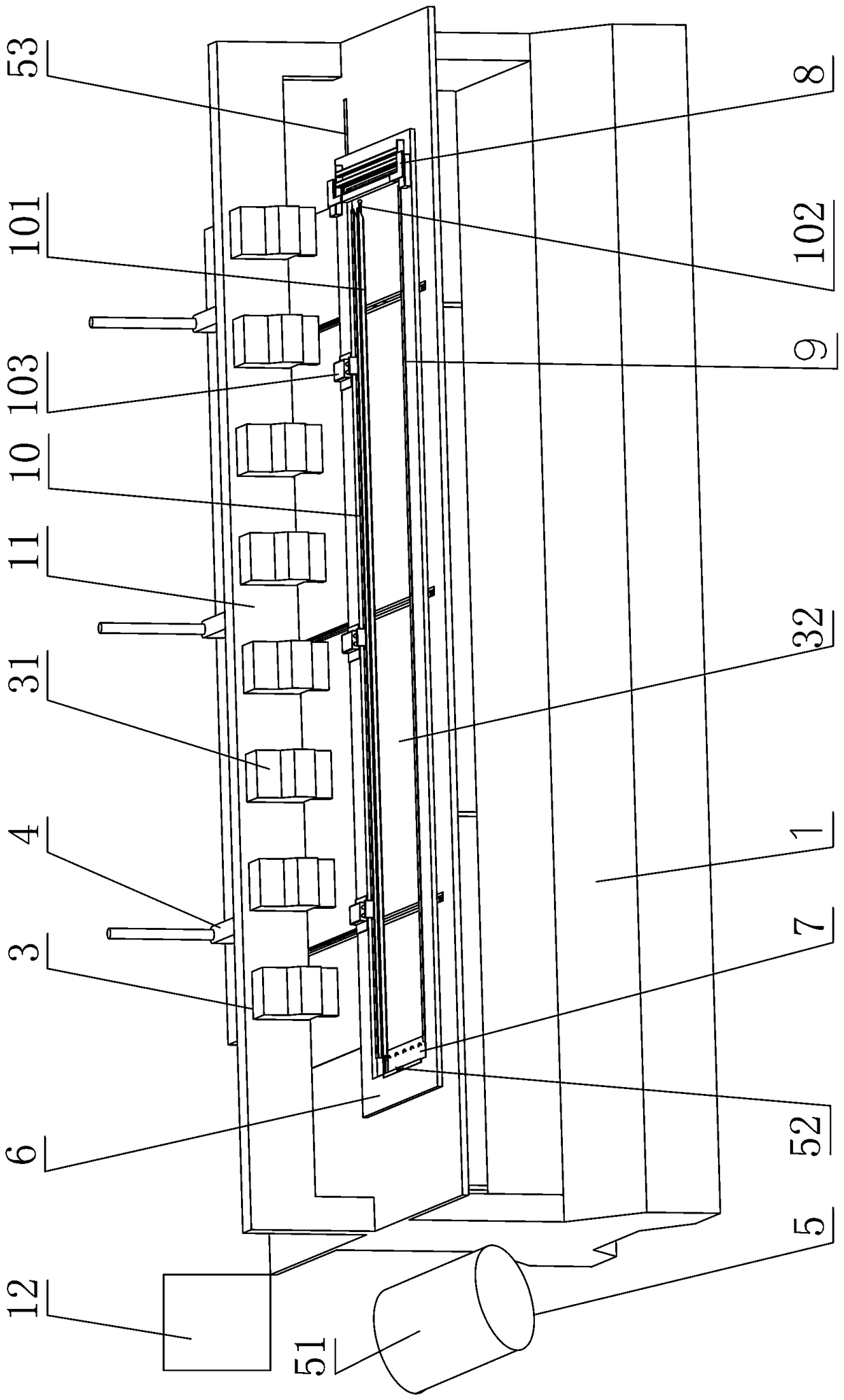
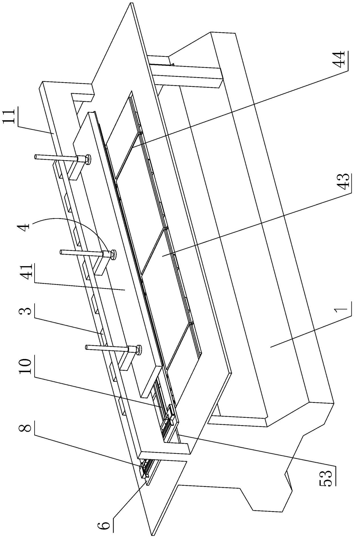
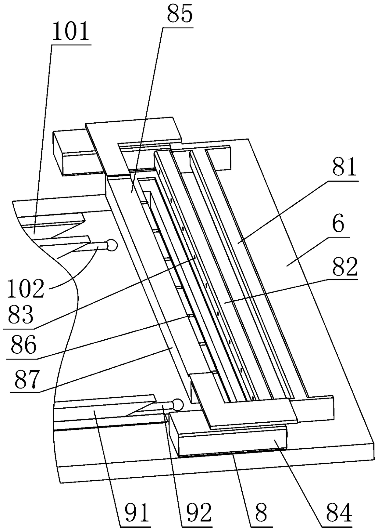
[0054] The present invention will be further described below in conjunction with accompanying drawing, according to Figure 1 to Figure 13 As shown, the tension feeding die-cutting automatic embroidery machine of the present invention includes a frame 1, a moving processing part, a tensioning part, a moving driving part 2, an embroidery part 3, and a pressing and cutting part 4 , receiving part 5.

[0055] The material receiving part 5 is installed on the left side of the frame, and the material receiving part 5 is provided with a tail hook knife 52 on the left side of the embroidery frame 6 .

[0056] Moreover, the embroidery component 3 and the pressure-cutting component 4 are respectively installed on the front side and the rear side of the beam 11 of the frame 1 . The mobile driving part 2 is equipped with a horizontal power conveyor belt 21 and a vertical power conveyor belt 22 connected to the bottom of the mobile processing part.

[0057] Wherein, the mobile processin...


PUM


Abstract

The invention provides a tension-feeding and die-cutting automatic embroidering machine and an operation method thereof. The tension-feeding and die-cutting automatic embroidering machine comprises amachine frame, a movable processing component, a tensioning component, a movable driving component, an embroidering component, a profiling cutting component and a material winding component, wherein amonitoring component connected with each component and used for controlling the running order of each component is arranged on the machine frame, so that automatic and cyclic completion of a series of processes of feeding, tensioning, embroidering, profiling cutting and material winding is achieved; furthermore, the tension-feeding and die-cutting automatic embroidering machine can also control the tension of the material according to the characteristics of the material to be processed so as to ensure the flatness during processing, is strong in adaptability and guarantees the embroidering effect; in addition, the tension-feeding and die-cutting automatic embroidering machine can also use a stamping cutting die for performing one-time overall profiling and cutting on a product, achieves precise and high-efficiency cutting and yclic automation, and is strong in adaptability, high in quality and high in efficiency.

Description

technical field [0001] The invention relates to the technical field of automatic embroidery machines, in particular to a tension-feeding die-cutting automatic embroidery machine and its operating method. Background technique [0002] Existing embroidery machines are generally computerized embroidery machines, which can repeatedly embroider cloth with high speed and high efficiency, or can repeatedly embroider partial areas, and thus are widely used. [0003] But, in actual application, existing embroidery machine has following deficiency. [0004] 1. Feeding and receiving materials are generally manual operations, which are complicated and affect embroidery efficiency. [0005] 2. Most of the fabric tensioning procedures are achieved by manually clamping the four sides of the fabric with clamps. The operation is cumbersome and labor-intensive, and the tension degree is controlled by the operator based on experience. It is difficult to adjust according to the texture of the ...

Claims


Application Information

Patent Timeline
IPC IPC(8): D05C5/00D05C13/00D05C9/06D05C9/16D06H7/00
CPCD05C5/00D05C9/06D05C9/16D05C13/00D06H7/00D05D2305/08
Inventor 严伟强
Owner 严伟强
Learn More